The first idea was that we would just recycle the abrasive. The particles of the target materials that were cut are generally much smaller than the abrasive particles themselves, and so it should be relatively easy to remove them from the mix. However, as we looked into the process in more detail, it was clear that it would not be quite as simple as it might, at first, appear. Marian Mazurkiewicz (retired) and Greg Galecki (who now runs the HPWL) carried out studies on the behavior of the particles as they moved through the mixing chamber and were accelerated down onto the target material. They found, as noted in an earlier post, that most of the abrasive was crushed to a smaller size when it passed through the cutting head, and a mix that started out with a particle size of 210 microns as it was fed into the system, was leaving the focusing tube with an average size of 140 microns.

Figure 1. Percentage of abrasive at different sizes after it has passed through a mixing chamber (and before it has hit the target). (After Galecki).
The reason that this is a concern is that, as the particles become smaller, so a point is reached where, depending on the target material, the abrasive no longer has sufficient energy to effectively cut into the target. When cutting into metals such as titanium and steel, our targets of choice in the study, this cut-off grade was at around 100 microns.
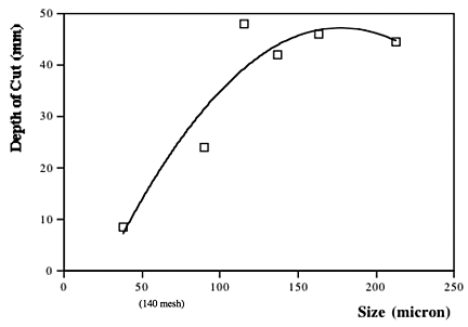
Figure 2. Effect of particle size on the cutting performance of an abrasive jet in cutting steel. (The tests were part of a factorial experiment and are thus averages over a number of different test runs at differing abrasive feed rates (AFR and pressures).
Roughly 25% of the mix in the example shown in figure 1 lies below 100 micron at it leaves the chamber. After impacting the target this value increases to more than 50%. Obviously recycling this fine material and re-using it in the cutting process is going to be less effective than removing it from the mix. Generally alluvial garnets will break up more rapidly than mined garnet, because of the structure of the abrasive particles, and thus the percentage that leave the focusing tube at the larger and more effective diameters are lower with the alluvial mix. The results were, we found, confirmed in the cutting results, with alluvial garnet producing a generally shallower depth of cut that would be achieved, other things being equal, in the cutting tests.
A quick word of explanation of the tests we ran, which are described in more detail here. The tests are run at a standard pressure and nozzle size, and at a constant traverse rate, with the depth that the jet cuts into a standard steel at a fixed speed measured over a 4-inch traverse length.
The results of the tests showed that, because of the particle crushing during the cutting process, the abrasive would have to be screened, and for most effective re-use only the larger fraction (on average less than 40%) should be recycled. The rest would be too fine for effective re-use in the operations we were developing. (Although finer abrasive has use in other applications, it would have to be screened and stored). It was interesting to note, and perhaps logical in retrospect, that once the particles had been used once and the larger ones separated out, then the percentage that survived and could be reused a second and third time increased significantly. This is mainly because those particles that had some form of weakness crack (either from weathering or from the mining process) were broken during the first impact, and the particles that survived did not have these cracks, and would therefore inherently be more prone to survive multiple times.
For our purpose, therefore, given that there was a high cost in purchasing the abrasive, and an even higher one in disposing of the contaminated material after cutting (because of the contamination by the target material) there was a potential economic advantage in recycling the abrasive. There were several ways in which the particles can be separated, but a simple screening process, if carried out properly, is quite time consuming, since the particles are required to “sit” on a vibrating screen for several minutes to ensure accurate separation, and this can be labor intensive if it is carried out as a batch process. We tried a number of different ways, including using a counter-flow fluid column that worked well for low feed rates, but the most efficient unit for one operation (we build virtually all of ours, and extensively modified them over time) may not be the best in other cases. (The one that survived the longest was a Wilfey table (though not this one).
In conventional AWJ cutting the abrasive has also to be dried before it can be re-used, and that can also add power and labor costs to the process. Thus, as with many choices that must be made when developing an efficient cutting operation, the best answer is to carry out a series of tests yourself, and run the numbers to decide whether, in the long run, recycling would, or would not, be an effective choice.


