Thursday, January 31, 2013

OGPSS - Coal power and air pollution

Fifty years ago I began my undergraduate studies at the University of Leeds in the UK. It is not something I particularly dwell on, but the stories out of Beijing this week, describing the air pollution in the Chinese capital, brought back a memory. The story on CNN notes that visibility in Beijing has been cut to under 200 yards. Back in Leeds in December of 1962 the air quality had registered the highest levels of sulfur dioxide in the air that had ever been recorded, as air conditions generated smogs that covered large parts of the country. What made it personal for me was that I lived about a mile from the University and had to walk there through the smog that covered the city. Despite it being daylight there came a point where I could not see (and I still remember doing this) my hand when held at the full stretch of my arm. Crossing the Park to the University there were cries in the mist, as folk fell over some of the, now invisible, decorative iron edging along the walkways. From that time on the air quality regulations took increasing effect, and before long the black buildings that I had walked past on my way through town were being cleaned and brought back to their original white condition, which they have retained in the years since.

Immediately after the Second World War Britain needed the coal to power the reconstruction of the country, but in the time that I was in college it was already clear that the days of unrestricted mining were over, and the transition to other fuels had already begun. It was not, however, the air pollution in Leeds that was the driving force for the regulations, but more likely the presence of similar smogs in London and the South, where those who governed the country lived. The major legislation began after the Great Smog of 1952. In a four-day period at the beginning of December the combination of a fog, an inversion in the immediate atmosphere, and the increased use of coal fires to provide additional warmth generated a smog that is blamed for the immediate death of around 4,000 people and a strong influence on the consequent death of some 8,000 others.

I bring this up because the air pollution in both Beijing, and in New Delhi is reaching levels where the government is beginning to move to help abate the immediate problem. In both capitals it is a combination of vehicle exhaust and power generation that is generating the problem, whereas back in the UK, fifty and sixty years ago, vehicular exhaust was not nearly as much of a problem as burning coal. Yet, I suspect that those problems in Asia are not yet at the levels that they reached in the UK, they may be less tractable of solution.

Burning coal to generate power remains a relatively simple process, as does mining of the coal, for which a realistic estimate would suggest that there remains, for now, a plentiful sufficiency. (That latter point is, however, disputed by some). The EIA has recently pointed out, that we are at a point where China is about to consume about half of the global supply of coal each year.


Figure 1. Chinese coal consumption relative to that of the rest of the world. (EIA)

At the rate of increase reported, it is likely that the two lines will cross before the end of this year. However it should also be noted that India has been importing more thermal coal than China (a projected 118 million tons for 2012, in contrast with the 102 million tons imported by China). And as Mongolian coal becomes more available, so India may take over parts of the international supply that now flows to China from Australia, Indonesia and Africa.

The need for increasing levels of power to sustain the growth rates of India and China are most often discussed in terms of the oil and natural gas that these two countries are consuming, but it has been estimated that India has a shortage of around 10% between the level of demand and actual supply, leading to crippling blackouts, such as that of last July.

It should be noted that the levels of air pollution from power generation can be controlled. The United States uses most of the roughly billion tons of coal a year that it produces for power consumption, but air quality has been successively cleaned to higher standards over the decades, so that smogs are now only a historic curiosity.


Figure 2. Coal consumption in the United States by end use. (EIA )

The efforts of the EPA, among others, have had a considerable impact on American Air Quality. This, for example, is the median air quality index for the District of Columbia over the past 30 years. (I am not sure where to get earlier data).


Figure 3. Median Air Quality Index for Washington D.C. (EPA )

It is thus, demonstrably possible for China and India to clean up their air, even as they increase their demand for coal. It should also be noted that over those past 30 years the miles that Americans drive has also increased, as I recently commented, and so, based on the above, the argument applies also to vehicular exhaust.

It is true that part of the imposed solution to date, in terms of the American coal used, has transferred demand to the lower sulfur coals of Wyoming, rather than the higher calorific value, but also higher sulfur contents of more Eastern states, but as regulations have changed the power plant requirements, so some of that earlier loss to Wyoming is being recovered.


Figure 4. The top coal shipping and receiving states in the third quarter of 2012 (EIA )

Based on American experience it is thus demonstrable that both China and India could clean up their air to American standards, while still generating the power that they need through burning coal. Unfortunately, however, as the experience with mine accidents in China has shown, there are still too many operations too far from Beijing for central regulation to be, as yet, fully enforced and complied with.

Addendum The Air Quality Index should be described. As the EPA Airnow site explains:
EPA calculates the AQI for five major air pollutants regulated by the Clean Air Act: ground-level ozone, particle pollution (also known as particulate matter), carbon monoxide, sulfur dioxide, and nitrogen dioxide. For each of these pollutants, EPA has established national air quality standards to protect public health .Ground-level ozone and airborne particles are the two pollutants that pose the greatest threat to human health in this country.

Figure 5. The gradation of the Air Quality Index. (EPA)

Read more!

Tuesday, January 29, 2013

Waterjetting 5c - flow straighteners

One of the advantages that became clear, even in the early days of waterjet use in mining, was that the jets cut into the rock away from the miner. It was thus a safer method of working, since it moved the person away from the zone of immediate risk. Rock has a tendency to fall when the rock under it is removed, and by using the jets to carry out the removal, so the miner is no longer as vulnerable.

But, in the early days of jet use the range of the jet was quite limited. Part of the reason for this is that the water is generally brought to the working place along the floor. It then has to be raised, through bent pipes, to the level of the nozzle, and then turned so that the water in the pipe is flowing in the direction in which the nozzle is pointing.


Figure 1. Sketch of an early Russian waterjet mining monitor

Even though the pressure of the jet is relatively low, the volume flow rates were high, and the bends leading into the nozzle set up considerable turbulence in the jet, so that the range of the jet was quite limited beyond the nozzle. There are a number of different ways of improving the range of the jet, and I will discuss these in later posts, and many of these techniques apply whether the jet is being used at high volume and low pressure for mining, or at higher pressures and lower flow rates for cutting into materials. But today the technique that I will discuss is the use of flow straighteners.

The two most dramatic instances that I immediately recall for their use were at the Sparwood mine in British Columbia, where the collimated jet was able to mine coal up to more than 100 ft. from the nozzle, and in an underground borehole mining application where a Bureau of Mines commissioned system was able to cut a cavity to more than 30 ft. from the nozzle, which was centrally located.

Collimating jets to get better performance is not restricted to the mining industry. A visit to Disney, for example, will find jumping jets that appear to bounce from place to place (video here) (this one shows the start of the surface waves along the jet, known as Taylor instability, which grow and cause the jet to break up; and if you want to make one Zachary Carpenter has two instructional videos on how they are made. (here and here.)

Essentially, as those Youtube segments show, the flow straightness is achieved by dispersing the water – using a sponge – so that it flows through a large number of drinking straws. These straws act to collimate the water flow, and it emerges as a glassy rod, which even acts as a light path so that light shone down it emerges at the far end. This can be used for a variety of different purposes, other than just for entertainment.

This then is the basic idea behind a flow collimator, although for larger mining flows drinking straws are too weak, and the flow volumes need to be larger. There are various designs that have been used for mining applications. Some of the earlier trials were at the Trelewis Drift mine, where the then British National Coal Board set up an experimental operation.


Figure 2. Sketch of Monitor used in the NCB Trials (after Jenkins, R.W., "Hydraulic Mining" The National Coal Board Experimental Installation at Trelewis Drift Mine in the No 3 Area of the South Western Division, M.Sc. Thesis, University of Wales, 1961.)

A number of different designs were used for the flow straighteners that were located at the nozzle end of the straight pipe section leading into the nozzle:


Figure 3. Designs for the initial flow straighteners used at Trelewis Drift (after Jenkins, R.W., "Hydraulic Mining" The National Coal Board Experimental Installation at Trelewis Drift Mine in the No 3 Area of the South Western Division, M.Sc. Thesis, University of Wales, 1961.)

More recent designs, which vary according to pressure, flow rate and pipe diameter, are a combination of those on the left above, and those on the right. It was such a combination that allowed the Canadian miners at Sparwood to achieve production rates of 3,000 tons of coal per shift as an average over the operation of a mining section.

While the use of flow straighteners does not give any gain over having a long straight section of pipe leading into the nozzle, it can bring the flow condition up to that level in places where the geometry (or the resulting unwieldiness of the pipe) would make the long entry impractical.

One of the more interesting applications of this is in the borehole mining of minerals. Simplistically a hole is drilled, from the surface down to the seam of valuable mineral. Then a specially designed pipe is lowered through the hole with the pipe having a nozzle set on the side. Then, as the pipe rotates, and is raised and lowered, the jet mines out the valuable mineral, which flows to the cavity under the pipe, where it is sucked into a jet pump and carried to the surface.


Figure 4. Schematic of a borehole mining operation (George Savanick)

As I mentioned at the top of the article, the jet cut a cavity some 30 ft in radius, with the jet issuing through a nozzle some 0.5 inches in diameter. In order to achieve this range it was important that the jet was properly collimated, yet the nozzle was set so that there could be no straight section.


Figure 5. Section showing the feed into the borehole miner nozzle. Note the vanes in the section leading into the nozzle (George Savanick).

The turning vanes to achieve the flow collimation were designed by Lohn and Brent (4th Jet Cutting Symposium) to produce a jet equivalent to that achieved had the nozzle been attached to a straight feed.


Figure 6. Turning vanes used to achieve a jet capable of cutting coal to 30-ft from the nozzle. (P.D. Lohn and D.A. Brent “Design and Test of an Inlet Nozzle Device” paper D1, 4th Int Symp on Jet Cutting Technology, Canterbury, BHRA 1978)

Tests of the performance of the nozzle showed that it produced a jet that was at least equal in performance to a nozzle with a straight feed, up to a standoff distance of 45 ft.

In simpler applications the designs do not need to be that complicated, for many simple spraying nozzles, for example, the straightener is made up of a simple piece of folded metal.


Figure 7. Simple flow straightener for use in low pressure and flow applications.

The water has now reached the nozzle, but that is not the end of the story of the feed system, as I will start to explain, next time.

Read more!

Wednesday, January 23, 2013

An unexpected short break

I have been traveling over the past week, and for a variety of reasons it is proving more difficult to get posts produced and posted than I had anticipated. We return from the land of elephant seals and "castles on the hill" at the beginning of next week, when a more normal circumstance will, hopefully, allow me to catch up on energy, waterjets and other matters. Thanks for your patience.

Read more!

Thursday, January 17, 2013

OGPSS - Miles travelled, gas used and OPEC

Leanan has noted the API report of the continuing drop in US oil demand. It would be wrong, I believe, to explain this purely by reference to the increased efficiency of vehicles now on the road, nor would it be realistic to expect that these changing conditions will result in a lowering of gas prices.

To explain the rationale behind these thoughts requires reference to two sets of data. The most potent is the behavior of the Kingdom of Saudi Arabia (KSA), but before discussing their actions the story begins with the changes in the miles travelled reports that are issued by the Federal Highway Administration each month. Driven by a comment on recent versions of that plot, it is worth revisiting the summary of the rolling total of miles travelled in the United States, with the October 2012 plot being the last available.


Figure 1. 12 month rolling total of miles driven on all roads in the United States (FHWA)

It should be noted that this is not the amount of fuel used, but rather the distance travelled, and thus in itself this does not reflect any changes in vehicle performance because of the increased efficiency of their engines.

And while there does not appear to be any great difference between the numbers for 2011 and 2012 when broken down by month, for rural and urban travel, they both lie below the values for 2010.


Figure 2. Travel on US Urban Highways by Month (FHWA)


Figure 3. Travel on US Rural Highways by month (FHWA)

This shows that folk are actually driving less than they have previously, which may be reflective of the current economic condition, when combined with the high price for gasoline in relative historic terms. One can compare these curves with the demand for gasoline from This Week in Petroleum., though this has data through the end of the year and has a slightly different lower scale range.


Figure 4, Demand for gasoline in the United States (EIA TWIP)

Demand for gasoline, as with miles travelled, seems relatively equivalent for data for 2011 and 2012. The demand for ethanol, on the other hand, seems to be significantly less, assuming production matches that demand.


Figure 5. Production of fuel ethanol in the United States (EIA TWIP)

OPEC take a keen interest in those activities in the United States that impact the demand for oil, and in their latest Monthly Oil Market Report (MOMR) have plotted the variation in oil price with miles driven:

Figure 6. US mileage plotted against the retail price of gasoline (OPEC January MOMR)

Driven by increased demands for vehicular fuel OPEC anticipates continued growth in domestic demand for oil, both in the Middle East, and in Latin America.


Figure 7. Increase in domestic oil demand in the Middle East over 2012 and 2013. (OPEC January MOMR)


Figure 8. Anticipated growth in domestic demand in Latin America (OPEC MOMR)

Both of these tables feed into and support the position that Westexas has discussed in regard to the drop in available exports of oil in the coming years.

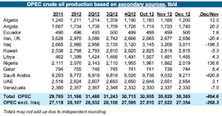
OPEC is not expecting to increase production in the coming year, but rather expecting that increase in demand will be met by production growth from the non-OPEC nations with numbers similar to those discussed earlier. And, as noted, most of that production growth is expected to come from America. The report confirms that OPEC, and particularly Saudi Arabia is willing to cut production, when demand falls, so that price levels are sustained. As in previous months the numbers showing production differ when the reports come from the countries themselves in contrast with reports from secondary sources.

Figure 9. OPEC crude production as reported directly. (OPEC MOMR )

There are significant drops in production reported for Iraq, Libya, Nigeria and Saudi Arabia so that the reported drop in production comes close to 1 mbd. There is not quite the same amount of sacrifice evident in the numbers from secondary sources.


Figure 10. OPEC crude production as reported from secondary sources (OPEC MOMR )

Overall production is down only around 500 kbd, with almost all of that being a reduction from Saudi Arabia. The difference between the production numbers from Nigeria (they report cutting production 120 kbd while others report they have increased production 136 kbd) are perhaps indicative of some of the problems that exist within the OPEC organization when they try and balance the supply:demand equation.

However, given that KSA is willing to do the heavy lifting it seems likely that prices will continue at their current levels, despite any changes in American production levels.

Read more!

Wednesday, January 16, 2013

Waterjetting 5b - hose connections and nozzle feed

There is often not a lot of choice, when laying out a project, over the path or distance that water must travel from the time it leaves the initial pump to the point where it reaches the nozzle and is usefully applied. Yet, over this length, if the right choices are made, some considerable improvement in performance might be achieved.

As discussed earlier, the simplest improvement is often just to increase the size of the delivery line, although there have been occasions where it was cheaper for us to use a double line rather than a larger single, in order to lower the friction loss to the nozzle, and keep operating pressure in the range that we needed.

There are other concerns with the layout of the feed line to the nozzle, If it is a hose, then any connections between sections should be whip-checked, so that should a coupling fail (which has been known to happen) then the released sections of hose will not whip around and cause injuries or other damage.


Figure 1. Hose that separated from a coupling, while under pressure.

The major risk comes at the moment of separation, while the pressure in the line is higher, before it drops under the larger area through which the water can now flow. To stop the whipping of the hose ends, the two should be restrained by attaching a cable with two loops that fit over either hose end making the connection.


Figure 2. Hose connection covered with a pressure dissipating sleeve (the blue cover) and with a whip connected to the hose ends on either side of the connection.

Apart from this, and remembering the possible risk about avoiding chaffing points and that, over time, high pressure tubing does fatigue (after many years of operation most of the pipe segments connecting between our ultra-high pressure pump and cutting table failed in a relatively short time period – but they all came at the same time, and were installed together and saw the same loading cycles). (Which emphasizes that, over time, the pressure rating of the tubing should be reduced).

Connections, T-joints and other fittings that are used in the feed line should be sized appropriately. Any time that the diameter of the flow channel changes, then there is a cost in terms of the delivered pressure. This is best checked with the manufacturer to ensure that this is accurately assessed in the flow and pressure calculations.

Moving down the line, this brings us to the end of the feed line, and the entrance to the nozzle. In later posts I will cover different pieces of equipment that can be used, for a variety of different tasks in manipulating the nozzle, but, for now, I would like to consider just the flow from the feed line into the nozzle (without discussing nozzle shape at this time).

Of all the systems I have examined, this is the one point in the assembly of a feed system that was most commonly ignored or badly constructed.

All of us, from time to time, get caught up in traffic flows through road construction. When the lanes are controlled, and traffic feeds are properly directed, it is possible to get through these relatively quickly. But in most cases that is not what happens. There are always drivers who do not ease into the required lanes soon enough, but rather drive rapidly as far as they can and then force their way into the remaining lanes, thereby breaking the steady flow into a process of stop-start-stop-start. The process becomes much less efficient, and instead of the traffic moving at a steady, but slow rate it often can take over half-an-hour or more to get through the restriction.

So it is with water flow down a pipe. If the flow can remain in a laminar mode, with the flow channel slowly constricted to speed the water up to the required velocity, then the resulting flow into and through the nozzle can give jet streams that can throw over 2,000 jet diameters. Instead in most cases the throw is about 125 jet diameters, and I will discuss how to find that distance in a post or two before long.

In this particular post the water has not reached the nozzle yet, and it could still be in a poor condition. The best way to explain why is to use a comparative graph showing jet pressure measurements after the jet has passed through the nozzle, to show how the structure is affected. The work was carried out by the Bureau of Mines (Kovscek, P.D., Taylor, C.D. and Thimons, E.D., Techniques to Increase Water Pressure for Improved Water-Jet-Assisted Cutting, US Bureau of Mines RI 9201, Report of Investigations, 1988, pp 10) and the only difference between the two different plots is that in the upper one a 4-inch straight length of pipe was connected just upstream of the nozzle to allow the flow to stabilize before it entered the nozzle.


Figure 3. The effect of flow conditioning the water, prior to passage into the nozzle.(Kovscek, P.D., Taylor, C.D. and Thimons, E.D., Techniques to Increase Water Pressure for Improved Water-Jet-Assisted Cutting, US Bureau of Mines RI 9201, Report of Investigations, 1988, pp 10)

There is a caveat to this plot, and this is the assumption that the internal diameter of the feed pipe and the entrance diameter to the nozzle are the same size. In virtually every system that I have examined in the field this has not been true, and as I will show, in a later post, the difference that this can make is very large. For the above example the length is 4-inches, but this was for a specific nozzle size, and the more general condition is that the length should be in the range of 100 – 125 pipe diameters.

By the same token, if the nozzle does not make up with the end of the feed line, so that there is a little eddy pocket created, the ensuing jet will be of poor quality.

Which brings us to the final part of this post, because there are many situations where it is not possible, because of space restrictions, to fit that particular length of pipe just before the nozzle. The most glaring example of this that we have had to deal with is where high-pressure waterjets are fed down a borehole, and then used to drill lateral excavations out from the bottom.

But if the borehole is say 10-inches in diameter, and the jet is an inch in diameter, because it is being used for mining out valuable pockets of uranium, then it is not possible to get the required straight section. Again the pioneering work on this was carried out, first in Russia, and then by the U.S. Bureau of Mines, under George Savanick. By placing a shorter length of a flow straightening device within the flow path, just before the nozzle, the flow can be straightened over a much shorter distance, and this will be the topic of the next post. And when George did this he was able to cut cavities that extended more than 30-ft from the borehole (with some unexpected consequences - but we'll cover that later - grin).

Read more!

Thursday, January 10, 2013

OGPSS - Happy New Year, or perhaps not!

It is the beginning of a New Year, and, belatedly, I hope that all readers find this new period to be one of prosperity, health and happiness. It would be encouraging if the portents for our Energy future would point in that direction, but unfortunately I can’t see nearly as much optimism in that regard as do others who are similarly reviewing where the global energy supply numbers are going. This week the EIA's ”The Week in Petroleum” is illustrative of the optimistic vision.


Figure 1. Recent projection from the EIA on American Oil Production (EIA TWIP Jan 9, 2013)

This plot is from the new Short-Term Energy Outlook from the EIA, which projects the numbers through to 2014, at which time: the Agency anticipates that US domestic production will rise to 7.9 mbd, the highest since 1988. Growth is expected to extend beyond just the Bakken:
In particular, drilling in tight oil plays in the Williston (which includes the Bakken formation), Western Gulf (which includes the Eagle Ford formation), and Permian basins are expected to account for the bulk of growth through 2014. Williston Basin production is expected to rise from an estimated December 2012 level of 0.8 million bbl/d to 1.2 million bbl/d in December 2014. Western Gulf Basin production rises from an estimated December 2012 level of 1.1 million bbl/d to 1.8 million bbl/d in December 2014. Within the Western Gulf Basin, roughly 0.4 million bbl/d of the oil production is outside of the Eagle Ford formation. The Western Gulf Basin accounts for more than half of the onshore domestic liquids production growth due to a comparatively large amount of liquids coming from both oil and gas wells compared with the other key production basins. The Permian Basin in West Texas, which includes plays such as Spraberry, Bonespring, and Wolfcamp, is a third key growth area. EIA estimates that crude oil production from the Permian Basin reached 1.2 million bbl/d in December 2012. Permian Basin production is projected to increase to 1.4 million bbl/d in December 2014.
The overall global concerns for production include a relatively small potential for production growth from the larger oil producers in the world (with the possible exception of Iraq), while there remains an increasing turmoil that began with the “Arab Spring” and continues to spread with ongoing and growing impacts that are likely on Middle Eastern oil production. But it is the story of American production that continues to gnaw at my worry bead string.

In context it should be remembered that, when The Oil Drum was first produced in 2005, national attention was briefly caught by the TV movie “Oil Storm” in which a plausible series of events – a hurricane in the Gulf, a ship collision in the Houston Ship Canal, and a terrorist attack on the Saudi oil terminal at Ras Tanura combined to raise the price of oil to a peak of $130 a barrel, and gas reached a final price of over $7 a gallon, with all sorts of terrible consequences. The day was finally saved when Russia shipped the US a few tanker loads of oil, after the US outbid the Chinese for that oil.

Since then there have been pundits who tell us that these things would never happen. During the real price rise to $147 a barrel (without the disastrous causes) we were reassured that prices would fall again to the $20-$30 a barrel range, though they have not – and those same pundits are now again parading before the media as they reassure us that the US can soon cast off the shackles of oil price control by foreign oil interests. Of the roughly 10 million bd that the US imported in October, some 4.2 mbd came from OPEC, Saudi Arabia sending 1.25 mbd, and Venezuela 0.95 mbd. Outside OPEC Canada supplied 2.68 mbd, Mexico 1.06 mbd and Russia 0.55 mbd. KSA has shown itself adept and willing to adjust flows to ensure that OPEC oil prices remain adequate, and there is no indication that they need or intend to change their approach. Any global increase in supply is likely to be more than offset by increases in demand from China and India, though the reality will be that as US demand declines (if it does) that displaced supply will transfer to meet Asian growth – and it will not then be available were the US projections to fall short, and the country have to increase imports again.

There are some troubling signs on the horizon that suggest the future US supply is not as robust as has been proposed. Chesapeake Energy, who have been a flagship for the development of natural gas, is in sufficient trouble that Aubrey McClendon, the CEO, will not get a bonus this year, amid a number of changes. Shares have dropped nearly 30% and as Art and others have noted, the economics are not as encouraging as the pundits would suggest.

The news from the Arctic is somewhat worse. Shell have been able to recover their drillship, which ran aground after losing its tow in a 70-knot storm with 40-ft waves, and it has now been moved to a safe harbor. The vessel must now be assessed and the program will be delayed. (This is particularly true as the investigations begin to line up, first was the Coast Guard, and now Interior.) The Alaskan Pipeline flows were averaging just under 583 kbd in November (December numbers are late), and that is up from the overall yearly average of 544 kbd, but is running at a 6% decline rate bringing problems in as little as 8-years. Although with monthly flow changing to improve conditions in the winter months, there may be more of a problem than is currently discernable, particularly if future supplies to keep the pipeline flowing are now threatened by the future losses of potential production from the Chukchi and Beaufort seas.

And speaking of pipelines the cancelling of plans for the Bakken Crude Express Pipeline for lack of customers tells more about the anticipated future demand than all the predictions from Dr. Yergin at Cambridge. Energy Research Associates. This also foretells that the Adelman prediction that technology will always return us to cheap oil, as touted by Phil Verleger is likely to continue to be proven false – not that these real events stop those who survive by predicting the future. Fortune tellers have been a facet of society throughout history, only the shape of their crystal balls has changed with time, and the size of their credulous audience.

Whether real or overly optimistic, the US potential increases in fossil fuel production is likely to impact to the potential for US renewable and bio-generated fuels, where the future production levels seem also to be losing their lustre. There is some talk of Dr. Chu leaving the Department of Energy in part perhaps because of this change in focus. However, among the names being floated are those of John Podesta, the founder of the Center for American Progress, who have just ranked their top ten Energy and Environmental Priorities for the first four years of President Obama’s time in office, as follows:


Figure 2. Priorities as quoted by the Center for American Progress.

And most recently the Secretary has been encouraging women and minorities to look at the wind energy industry as an opportunity for employment.

One other candidate is apparently Bill Ritter, the past Governor of Colorado, although the list, at this point, seems to be growing rather than shrinking.

Whether under either individual, or some alternate choice, the next four years of President Obama’s Administration will likely see many more changes than anticipated as occurred during the first term. It is, however, discouraging that there are so few possibilities for realistic optimism for that future.

Read more!

Sunday, January 6, 2013

Waterjetting 5a - Making gift items

There is a time, which can come in late Winter and very early Spring, when demand declines and there is some free time for the occasional home project. Although many of us now know and understand how well waterjets and abrasive waterjet streams can cut material, this is still not that widely recognized by the General Public. This slack time can help to remedy that problem.

Uninformed ignorance of jet capabilities was certainly true for many years on our campus, and seems to become more so again as the years pass since I retired. Further, at Conferences, I often heard the complaint that the industry needs to get its message out more clearly to a wider audience. The vast majority of potential industrial users are unaware of how well waterjetting in one of its forms could help solve their problems.

Now there are lots of ways of solving that problem, but today I want to talk about just one, the one we used to help us with the problem. It had to be something that would be used by those we gave it to. It had to be small, relatively cheap and quick to make, and yet demonstrate some of the capabilities we wanted to show off. The answer ended up as a business card holder.


Figure 1. Business Card Holder - Missouri Miner female figure.

University labs are generally cash strapped, and so the material had to be relatively cheap, so we used sheets of a light foam. This allowed us to cut out the figure parts using water alone (at around 20,000 psi) which significantly reduced the cost. Early in the design of the female figure (this was the third in a series , where we cut a different shape each year) it was pointed out that relative body size was more critical with female figures, and so two different thicknesses of foam were used. The first was half-an-inch thick and used for the body and pins, while a quarter-inch sheet was used for the legs and arms.


Figure 2. Foam miner front view – showing the two thicknesses of material

Putting a small hole in the position of the eye allowed the model to show how precise and small a cut could be made through thicker material. The five pieces that made up the total were held together with two rectangular pins that were cut from the thicker stock and fitted through slots cut to their shape in the different parts.

One of the advantages of cutting these (and we cut parts for around 300 figures, and used virtually all of them each year) is that it was also possible, with relatively little trouble, to cut the campus identifier on a leg of the figure. With not a lot of space this was originally UMR, and then changed to “S & T” when the campus changed its name.


Figure 3. A later model of the card holder with the campus ID cut into the leg.

For speed in cutting we only cut the letters in half the legs, though you may note that in this later version we also cut the connecting pins as round rod, rather than rectangular. In this way the figure could be repositioned, as the owner decided what they wanted to do with them.

Basically however they served as card holders, and having passed them around, (and provided them to senior campus officials as place card holders for dinner meetings) it has been amusing to see how avidly they were sought and kept by some of those to whom they were given.

Now we did not get to these figures in one step. The initial idea was to carve something out of rock, since the overall department was known as The Rock Mechanics and Explosives Research Center. However, if you are making something out of rock, particularly a person’s shape, they need to be larger, because of the weak strength of the rock.


Figure 4. Comic-book Miner cut out of Missouri Granite

The cost was also high, since the cuts had to be made with abrasive, and the rock had to be polished before it was cut. (Trying to polish the pick points after cutting led to several breakages, and this is something that is either perfect or worthless).

There are several good ideas that individual companies have, that help sell their name and capabilities where the gifts are of metal, and can be used for opening bottles or of some other benefit. But we could not afford the cost to cut a lot of pieces using abrasive, and nothing that we tried in metal had the cachet of the small miners.

In this case the mascot of the campus is the Missouri Miner, and while the first model that we cut followed along the shape of that cartoonish figure, many of our graduates were going into coal mining, which is also my background, and so the second and third versions had coal mining helmets, and as a further demonstration of capabilities, a small circular cut in the helmet allowed a yellow rod to be put into the helmet to illustrate the miner’s cap lamp.

Where we were asked to prepare small souvenirs for another event we did use the Missouri Granite, but had learned this time to buy tiles that were already polished. Then all we had to do was to cut the shape of the state into the tiles, and then put a University logo sticker on the piece and we had our memento for the guests.


Figure 5. Small memento of the state shape carved out of granite tile.

This was for a specific occasion where the sponsor was willing to pay for both the cutting costs and the materials, but in order to keep costs down (since these were given away) the pieces had to be small. This particular run was one of the more difficult to keep inventory on, since several disappeared during the short time of the cutting runs (which we have found is an occupational hazard with “artistic” pieces where there are lots of temporary folk involved in our work).

Which is, I suspect, an entry for the last piece of advice on making such gifts, and that is to plan on making more than you think you need, and, if possible, be able to make more if needed. In a later post I will write about where you can get some artistic help for relatively little cost to help with ideas such as this.

Read more!