Figure 1. Looking down into a channel cut by a cavitating jet that traversed from left to right, at a speed of 0.4 inches/minute. Note the preferential attack into weakness planes within the rock.
As the weakness planes grow and join, so individually larger pieces of rock can be broken free from the target and the path, and pressure profiles of the water in the cutting zone change quite significantly. For this cavitation to have a significant impact on the erosion pattern, however, the traverse speed over the surface must be controlled, and be relatively low. At more effective speeds the cutting process does not allow for the development of this fracture mechanism. Rather, with plain jets, the process concentrates just on crack growth around individual grains. Optimum cutting speeds are much higher, depending on the intended result.
The efficiency of waterjet cutting has, historically, been assessed in terms of how much energy is required to remove unit volume of material. This we call the specific energy of the cutting process, and a common unit is joules/cubic centimeter (j/cc). When using a waterjet to cut into material, in part because of the interference between different segments of the jet stream, pre and post impact, the most efficient cutting speeds are quite high.

Figure 2. The change in cutting efficiency with traverse speed of a high-pressure waterjet cutting stream
The downside to using higher cutting speeds (apart from the simple inertial problems in driving systems at higher speeds in other than straight lines) is that the depths of cut achieved become smaller on individual passes, as the jet has less cutting time on each path increment.

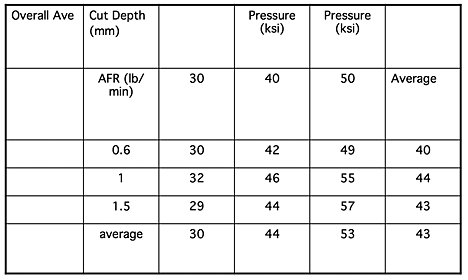
Figure 3. Change in cut depth as a function of traverse speed, for varying different rock types.
In linear cutting systems it is sometimes possible to align secondary or a higher multiple array of nozzles along the cut, so that thicker materials can be cut with a sequence of jet cuts along the same path. Alternately a single nozzle can make multiple passes along the cut path and sequentially deepen the slot.
Unfortunately while this is an effective way of solving some problems, it becomes less efficient as the slot gets deeper.

Figure 4. The change in cutting efficiency with increase in the number of cutting passes.
At higher pass numbers with the target surface at a growing distance from the nozzle, and with the edges of the cut starting to interfere with the free passage of the jet to the bottom of the cut, less energy is arriving at the bottom of the slot and thus the effectiveness falls.
While there are differences between abrasive waterjet cutting (where the optimal cutting speed is much lower than that for a plain high-pressure water jet) the form that the cutting jet takes through the target material is of similar shape in both circumstances.

Figure 5. An abrasive waterjet cut through 1-inch thick glass
As the jet cuts through the piece, so the cutting edge curves backwards from the top of the cut to the bottom. The rate of this curvature is, inter alia, a function of how fast the nozzle is moving over the surface. Dr. Ohlsson showed this effect in cutting through 0.4-inch thick aluminum and mild steel plates, back as part of his doctorate at Lulea in 1995.

Figure 6. Change in the cutting edge profiles and cut groove patterns in metals as a function of cutting speed (L. Ohlssson PhD Lulea, 1995)
The growth of the striations in the cut surface, as the depth of cut increases is one of the larger concerns with cut surface quality, since customers are often concerned that these be minimized, and further if they become large enough they can make it difficult to separate the pieces, particularly if the parts are cut with a complex geometry.
Early in the understanding of the way in which waterjets work, it was thought that the jet would incrementally cut strips from the material in front of the previous cut, inducing steps into the cutting plane that worked their way down the material.

Figure 7. Early concept of cutting front development (L. Ohlssson PhD Lulea, 1995)
However, as higher speed cameras recorded the development of the cutting front, this concept has been rethought. Henning, for example at the 18th ISJCT, used a camera taking 520 frames per second to establish the development of the cut profile as the jet cut through clear plastic. In figure 8 the profiles are shown as they developed at 35 frames/sec to allow them to be distinguished.

Figure 8. Cutting front development as an abrasive jet cuts from right to left (Henning 18th ISJCT)
As Ohlsson had shown this profile develops as the abrasive laden jet impacts then bounces, then impacts and cuts further into the material, as it moves down the cut.

Figure 9. Frames showing a sequence as an abrasive waterjet cuts through 2-inches of glass. ((L. Ohlssson PhD Lulea, 1995)
In his work Henning correlated the change in the “bounce angle” with the jet properties, while Ohlsson also correlated with the traverse speed.

Figure 10. Change in the “bounce” angle as an abrasive jet moves down the cut (Henning 18th ISJCT)
Two things should be remembered in this analysis, since they also explain causes of the increased roughness of the cut each time the jet bounces. The first is that the jet is not only laden with any initial abrasive, but as it cuts into the material, and removes it so that cut material is entrained in the jet, so that there is some abrasive cutting, even with a plain waterjet once the initial cut has been made. The second point is that when the jet bounces it is not constrained to bounce just in the plane of the cut, but can and does take up some deflection into the sides of the cut. Thus, with each bounce and reflection, the cut becomes rougher as that side cutting becomes more pronounced.
However the number of bounces can be slowed by slowing the speed at which the nozzle moves over the surface.

Figure 11. Change in the angle along the cutting edge as the speed of cutting and the jet pressure are changed (H. Louis, Waterjet Conference, Ishinomaki, 1999)
Henning uses a different term, but nevertheless it is clear that increasing the jet pressure and changing the diameter of the jet stream also controls the edge profile, and as discussed, with a smaller number of bounces so the edge quality improves.

Figure 12. The effect of changing jet pressure and jet diameter on the gradient of the cutting edge profile (Henning 18th ISJCT)