Before the process could begin, however, it was necessary to significantly modify the blow-out preventer (BOP) that sits on the top of the well. For those interested (its a bit like watching one of the operations on the space station) BP has assembled a short (5 minute) selection of the video footage of the various steps. When watching it, you should bear in mind that the ROV’s carrying out the different steps have to operate in a relatively crowded environment.
 The well neighborhood
 The tasks to be done included removing, modifying and replacing the control box (or pod) that operates the valves that open and close the flow lines into the choke and kill lines on the well. Other than this, the flow lines to the flow and choke lines themselves had to be replaced with the feed lines (shown in the animation) that will carry the mud into the well. Even tightening a fitting that had worked loose takes time, when it has to be done using an ROV (with the operator at the surface needing to see what he is doing while getting the ROV to hold the necessary wrench and turn the fitting). The old feed lines then had to be cut from the BOP, and replaced.
 ROV image showing the control pod fitting being tightened
This involved
* cutting off the choke and kill line connectors
* Cutting the bolts on a flange
* Removing the clamp
* Removing the pipe flange end
* Buffing and cleaning the pipe end
* Preparing to attach the new jumper lines. (This had to be done for each feed line)
* A special hydraulic connector attached to the 150-ft jumper cables was used to latch onto the old inlets. This is slow work (as the video shows) and as a result this part of the work has taken seven days. (The jumper shown in the video was attached on the 16th and chained down into position on the 17th.)
When the connections and fittings have all been made and checked, and the control pod operation validated, and the necessary permits from MMS and others obtained, then the process can begin.
The process will be controlled from the Q4000, which is designed to have the capabilities needed. Two lines feed from the vessel to the BOP. The first carries the control feeds through an umbilical, while the second is a riser that carries the mud down to the flexible hoses and jumper lines into the BOP itself. This mud, at about twice the density of water, will be delivered from the two high-pressure Schlumberger MD 1000 mud pumps made by Schlumberger and will flow through the two feed lines that were the choke and kill circuits, into the well itself, below the main rams of the BOP.
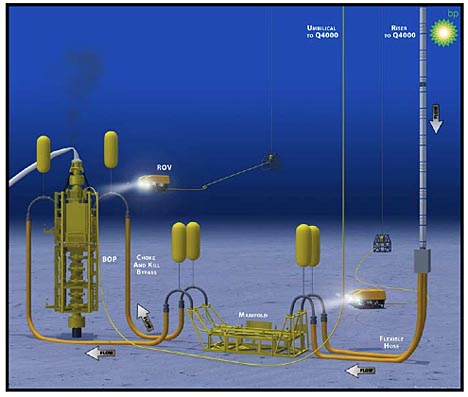 Top Kill Circuit
 The pumps will deliver the mud into the lines at a pressure of 6,800 psi, but as Kinuachdrach has correctly noted, it will then acquire the pressure from the full 5,000 ft column of mud as it flows down to the BOP, and enters the flow channel carrying the oil. Now we know that the BOP rams at least partially closed. If they are planning on using golf balls for the “junk shot”, it is feasible to surmise that the maximum width of the flow channel is no more than a third of a golf ball diameter. Not arguing the merits of American vs British ball sizes, let us assume that this is roughly half-an-inch (though it may have a greater length).
However, as flow volumes go up it requires more and more pressure for the fluid to get through a small gap. And at a given delivery pressure, only a certain flow volume will thus be able to escape that way. As long as this pressure exceeds that in the well, the net result will then be that the mud begins to push the oil and gas back down the well, and the well fills up with mud. The weight of that mud should then be enough to exert a pressure on the bottom of the well that is enough to exceed the fluid pressure in the rock and therefore stabilize the well and stop the flow of fluid out. Cement can then be pumped into the well to seal the top end. (Or with the flow stopped another BOP can be put on the well to seal it). The main worry is that the hole in the top of the BOP is small enough to contain the additional flow volumes, and not allow the entire flow to escape upwards rather than being forced down the well. The higher flows might, in addition, if they do exit the riser, further erode the openings. This could increase the oil flow, as it lowers the resistance. (If this happened then the LMRP will be deployed).
There are, however , a number of caveats to this operation. If the pressure in the well gets too high it can cause fractures in the rock at the bottom of the well, and this can cause the mud in the well to flow into the rock, rather than sitting in the well holding the pressure against the oil pressure.
There are also concerns with the condition of the bottom of the well, and whether this will have any impact on the flow of mud back down to the well and in sealing it.
Suttles said BP could not be certain but diagnostic tests on the well seem to indicate the flow is not coming up the main bore.
The well also contains obstructions that are restricting the flow rate.
It is impossible to know for certain what those obstructions are, Suttles said, but cured cement and rocks from the formations that crews drilled through could be partially clogging the well.
If the top kill fails, then the next step will be to cut off the riser, and use the top hat that is sitting on the sea bed near the well, to capture the flow in the LMRP option.
 The Lower Marine Riser Package (LMRP) option
 Were it me, I might contact Atlas Tocco and have them look into connecting up an induction heating coil around the outside of the bottom of the riser section. Might give them the occasional additional bit of heat on the inside surface that might be needed to dislodge any inconvenient crystals that might form., without interfering with the internal flow channels.
As a point of scale for the video from the riser leak, the amount of dispersant that is being ejected into the water is about 14,000 gallons a day or about 10 gallons a minute (quarter of a barrel roughly). A 5,000 bd flow is around 150 gals/minute.
This came from Doug Suttles teleconference in which he noted that BP have now spent around $800 million. He noted that oil levels in the water near the well are being measured at 10 ppm )(parts per million), against an EPA limit for oil discharge which is 15 ppm. However it is early in the monitoring cycle, and with a fleet of government sampling vessels now starting to work, the plumes and oil dispersant paths will be mapped in more detail in the weeks ahead.


No comments:
Post a Comment