Showing posts with label steel. Show all posts

Tuesday, February 19, 2013

Waterjetting 6b - The Triangle comparison test

This post is being written in Missouri, and while the old saying about “I’m from Missouri, you’re going to have to show me,” has a different origin than most folk recognize*, it is a saying that has served well over the years. We did some work once for the Navy, who were concerned that shooting high-pressure waterjets at pieces of explosive might set them off, as we worked to remove the explosive from the casing. We ran tests under a wide range of conditions, and said, in effect, “see it didn’t go off – it’s bound to be safe!” “No,” they replied, “ we need to know what pressure causes it go off at, and then we can calculate the safety factor.” And so we built different devices that fired waterjets at pressure of up to 10 million psi, and at that pressure (and usually a fair bit below it) all the different explosives reacted. And it turned out that one of the pressures that had been tested earlier was not that far below the sensitivity pressure of one of the explosives.

That is, perhaps a little clumsily, a lead in to explain why just getting simple answers, such as “yes I can clean this,” or “yes I can cut that” doesn’t often give the best answer. One can throw a piece of steel, for example, on a cutting table, and cut out a desired shape at a variety of pressures, abrasive feed rates (AFR) and cutting speeds. If the first attempt worked then this might well be the set of cutting conditions that become part of the lore of the shop. After a while it becomes “but we’ve always done it that way,” and the fact that it could be done a lot faster, with a cleaner cut, less abrasive use and at a lower cost is something that rarely gets revisited.

So how does one go about a simple set of tests to find those answers? For many years we worked on cutting steel. Our tests were therefore designed around cutting steel samples, because that gave us the most relevant information, but if your business mainly cuts aluminum, or titanium or some other material then the test design can be modified for that reason.

The test that we use is called a “triangle” test because that is what we use. And because we did a lot of them we bought several strips of 0.25-inch thick, 4-inch wide, ASTM A108 steel so that we would have a consistent target. (Both quarter and three-eighths thick pieces have been used, depending on what was available). The dimensions aren’t that important, though the basic shape that we then cut the strips into has some advantage, as I’ll explain. (It later turned out that we could have used samples only 3-inches wide, but customs die hard, and with higher pressures the original size continues to work).

>br>Figure 1. Basic Triangle Shape

The choice to make the sample 6-inches long is also somewhat arbitrary. We preferred to make a cutting run of about 3 minutes, so that the system was relatively stable, and we had a good distance over which to make measurements, but if you have some scrap pieces that can give several triangular samples of roughly the same shape, then use those.

The sample is then placed in a holder, clamped to a strut in the cutting table, and set so that the 6-inch length is uppermost, and the triangle is pointing downwards.


Figure 2. The holder for the sample triangle.

The nozzle is placed so that it will cut, from the sharp end of the triangle, along the center of the 0.25-inch thickness towards the 4-inch end of the piece. The piece is set with the top of the sample at the level of the water in the cutting table. The piece is then cut – at the pressure, AFR, and at a speed of 1.25 inches per minute, with the cut stopped before it reaches the far end of the piece, though the test should run for at least a minute after the jet has stopped cutting all the way through the sample.

The piece is then removed from the cutting table, and, for a simple comparison the point at which the jet stopped cutting all the way through the triangle is noted.


Figure 3. Showing the point at which the jet stopped cutting through various samples, as a function of the age of the nozzle – all other cutting conditions were the same. (A softer nozzle material was being tested, which is why the lifetime was so short). The view of the samples is from the underside (A in Fig 1.)

An abrasive jet cuts into material in a couple of different ways - the initial smooth section where the primary contact occurs between the jet and the piece, and the rougher lower section where the particles have hit and bounced once on the target, and now widen and roughen the cut. Since some work requires the quality of the first depth, we take the steel samples, and mill one side of the sample, along the lower edge of the cut until the mill reaches the depth of the cut, and then we cut off that flap of material, so that the cut can be exposed. Note that the depth is measured to the top of the section where the depth varies.


Figure 4. Typical example of a steel triangle that has been cut and then sectioned to show the quality of the cut.

I mentioned, in an earlier article, that we had compared different designs from competing manufacturers. Under exactly the same pressure, water flow and abrasive feed rates, the difference between the cutting results differed more greatly than had been expected.


Figure 5. Sectioned views of six samples cut by different nozzle designs, but at the same pressure, water flow, AFR and cutting speed.

There was sufficient difference that we went and bought second, and third copies of different nozzles and tested them to make sure that the results were valid, and they were confirmed with those additional tests. Over the years as other manufacturers produced new designs, these were tested and added into the table – this was the result after the initial number had doubled. (The blue are results from the first nozzle series tests shown above).


Figure 6. Comparative depths of cut using the same pressure and AFR but twelve different commercially available nozzle designs.

There were a number of reasons for the different results, and I will explain some of those reasons as this series continues, but I will close with a simple example from one of the early comparisons that we made. We ran what is known as a factorial test. In other words the pressure was set at one of three levels, and the AFR was set at one of three levels. If each test ran at one of the combination of pressures and AFR values, and each combination was run once then the nine results can be shown in a table.
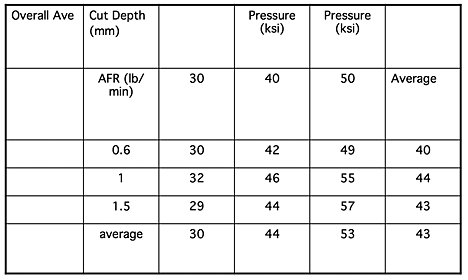

Figure 7. Depths of cut resulting from cutting at jet pressures of 30,000 to 50,000 psi and AFR of 0.6, 1.0 and 1.5 lb/min.

The results show that there is no benefit from increasing the AFR above 1 lb/minute (and later testing showed that the best AFR for that particular combination of abrasive type, and water orifice and nozzle diameters was 0.8 lb/minute).

Now most of my cutting audience will already know that value, and may well be using it, but remember that these tests were carried out over fifteen years ago, and at that time the ability to save 20% or more of the abrasive cost with no loss in cutting ability was a significant result. Bear also in mind, that it only took 9 tests (cutting time of around 30 minutes) to find that out.

__________________________________________

* The reason that the “I’m from Missouri, you’ll have to show me,” story got started was that a number of miners migrated to Colorado from Missouri. When they reached the Rockies they found that, though the ways of mining were the same, the words that were used were different. (Each mining district has its own slang). Thus they asked to be shown what the Colorado miners meant, before they could understand what the words related to.

Read more!

Friday, September 28, 2012

Waterjetting 1d - Not quite that simple!

When I first began the research on the applications of high-pressure water that was be one of the major parts of my professional life I must confess to a certain naïve innocence in regard to other folk’s work. One assumed that other folk had made similar mistakes to mine, and then corrected them, so that when different systems were compared that the early, obvious, mistakes had not been made.

One of the first times I found that this wasn’t the case was when we were asked to go and demonstrate that high-pressure waterjets could economically cut granite, in quarries located in the heart of the Granite industry, in Elberton, Georgia. We were working with Georgia Institute of Technology (Georgia Tech) at the time and were asked if we could, at very short notice, go down to a couple of quarries and run a demonstration.

Back during my graduate studies I had found that Russian claims were true that said that it was possible, with a 10,000 psi jet pressure to cut through a rock with a compressive strength of 30,000 psi. (I'll tell you how later)


Figure 1. 9-inch thick block of granite drilled through by a 10,000 psi waterjet at Leeds University. It took over 30 minutes. (Summers, D.A., Disintegration of Rock by High Pressure Jets, Ph.D. Thesis, Mining Engineering, University of Leeds, U.K., 1968.)

Knowing this, and having a suitable pump at Rolla, our group ran some tests at the RMERC to get the angles right between the two jets that we were to use, and then, about a week later, we went down to Elberton and set up a system in the quarry.


Figure 2. Starting to cut a 1-inch wide slot in granite, pressure 14,000 psi, 90 rpm, linear cutting speed around 9 ft/min, areal cutting rate around 20 sq. ft./hour.( Raether, R.J., Robison, R.G., Summers, D.A., "Use of High Pressure Water Jets for Cutting Granite," 2nd US Water Jet Conference, Rolla, MO., April, 1983, pp. 203 - 209.)

The trials demonstrated that high-pressure water could cut granite at commercial rates, we cut a slot some 11 ft long and about 2-ft deep, and, after a couple of days of work, we went home. Georgia Tech then went to one of our competitors who set up to run a similar test. We had been done in 2 days, it took them two weeks to cut a slot about 2 ft long and 6-ft deep. They were running a jet system at 45,000 psi, roughly 3 times the pressure of our system. Why did they do so badly?

Well it turned out that they connected their pumps to the nozzle through a very narrow length of high-pressure tubing, and we calculated (as later did they) that of the 45,000 psi being supplied at the pump, some 35,000 psi had been lost in overcoming friction between the pump and the nozzle, As a result they were trying to cut the granite with jets at a pressure of 10,000 psi effective pressure, and it was much slower than our system which retained most of the 14,000 psi from the pump to the nozzle. (Hilaris, J.A., Bortz, S.A., "Quarrying Granite and Marble using High Pressure Water Jet," paper D3, 5th International Symposium on Jet Cutting Technology, Hanover, FRG, June, 1980, pp. 229 - 236.)

Now you may note that I said something about mistakes – it turns out that we had made an identical mistake a few years earlier and had added a second 10-ft length of narrow diameter tubing to the nozzle, and suddenly a system that had cut adequately with 10-ft of tubing did not work with 20-ft. The reason was the pressure loss in the tubing was too great at the longer length, and the pressure fell below that required to cut into the rock. (But at the shorter length we were drilling the hard sandstone at 12-ft/minute).

It is a very simple mistake, and many folk have made it over the years. The system has to be designed from one end to the other to ensure that all the parts are properly sized for the systems that are to be used. (And I will refer to other cases such as that above as we go through this series.)

It is not just the diameter of the feed lines that is important. In 1972 it took, on average, 150 man-hours and about $2,000 for the U.S. Navy to clean a single ship boiler using chemicals and mechanical scrubbing and cleaning. An enterprising company showed the Navy that it was possible to use waterjet lances to clean the tubes. In the demonstration they cleaned a boiler in 10 hours, and it cost around $700. This being Government work, the Navy then arranged a competition to find the most effective contractor. Based on the performance of the system that had been used in the first demonstration they asked 5 companies to compete in cleaning boilers. The operating equipment was designated as having to operate at 20 gpm, at a pressure of 10,000 psi. The results were not even close, even with systems nominally the same.


Figure 3. Relative cleaning efficiency in areal percentage cleaned, of five competing systems in cleaning heat exchanger tubes in Navy boilers. (Tursi, T.P. Jr., & Deleece, R.J. Jr, (1975) Development of Very High Pressure Waterjet for Cleaning Naval Boiler Tubes, Naval Ship Engineering Center, Philadelphia Division, Philadelphia, PA., 1975, pp. 18.)

One of the differences between the competing systems, you won’t be surprised to hear, was that some had smaller feed hoses than others.

There are many different reasons that the various systems performed as they did. One of the aims of this series is to ensure that, should you be asked to engage in such a competition, you will know enough to follow the path of company A, rather than company E.

As systems have become more sophisticated the different factors that control the performance of the jets have increased in number. As a simple example, when abrasive particles are mixed with high-pressure water in streams of abrasive-laden waterjets at pressures that can run up to 90,000 psi in pressure, for high precision cutting of material, the factors controlling performance now include not only the delivery system for the water, but also that for the abrasive, the type of abrasive and the configuration of the nozzle through which that final cutting jet is created.

Again, when we were asked to compare the performance of these different systems we set up nominally identical test conditions under which to determine which nozzle system would perform better. If I were honest I would tell you that before the tests began I expected that the variation in performance of the systems would vary by perhaps 10% between the best and the worst. We were quite surprised by the result.


Figure 4. Comparative performance between 12 nominally similar abrasive waterjet cutting nozzles in cutting through steel at a standard speed, pump pressure, and abrasive concentration.

I use these last two figures to show that all the details of a high-pressure waterjet system are important, when it comes to optimizing performance. One of the reasons to write this series is to ensure that folk that use these systems in the future do not make the mistakes that we made, as we learned how to tune the systems from getting poor performance to the commercially viable rates that are achieved today.

Unfortunately much of the early research and tests that are the basis for this knowledge were performed before the Internet existed. As a result I will have to use references to books and papers (as above) rather than using the electronic references that are the more common habit now.

This concludes the basic introduction to the series, which will now focus on more specific subjects.

Read more!