Showing posts with label AFR. Show all posts

Tuesday, December 10, 2013

Waterjetting 16b - Optimum Abrasive Feed Rate and Depth

The post that I wrote last week was focused on the misperception that you need to add more abrasive to an abrasive waterjet if you wish to cut through thicker material. This is wrong on a number of counts, but most particularly because a good operator will have tuned the nozzle to achieve the best cutting jet, based on pressure and abrasive feed rate (AFR) regardless of target material. What the operator may change is the operating pressure (which would change the optimum AFR) and the traverse speed since these control the depth and quality of the cut that the jet makes.

But, before leaving the topic, I would like to discuss, in a little more detail, the concept of the optimal amount of abrasive that one should use with a given jet, and what happens as that feed rate is changed. As I mentioned last time, because of differences in the shapes of the mixing chambers of the nozzles supplied by different manufacturers, the specific sizes and optimal flow rates will differ from nozzle to nozzle but the overall conclusions remain the same.

Last time I pointed out that the driving waterjet had to break up within the mixing chamber in order to properly mix with the abrasive and to bring this up to a maximum speed before the mix left the focusing tube. Where the driving jet is too large then this breakup is not complete and the mixing is not efficient. As a result the jet that comes out of the end is more diffuse and the abrasive will not have reached the full velocity possible. However, if the incoming waterjet is made smaller for the same AFR and other mixing chamber geometries, then the cutting performance will decline.


Figure 1. Effect of increase in jet pressure when cutting aluminum with an AFR of 1.7 lb/minute (after Hashish, M., "Abrasive Jets," Section 4, in Fluid Jet Technology- Fundamentals and Applications, Waterjet Technology Association, St. Louis, MO, 1991.)

For a similar reason adding a polymer to the jet fluid should only be carried out with some care for the consequences. Long-chain polymers can give a jet increased cohesion and this can, at high enough concentrations, inhibit jet breakup in the mixing chamber thus reducing the effectiveness of mixing in the chamber.


Figure 2. The effect of changing cutting fluid on AWJ performance (after Dr Hashish ibid)

Polyox, (polyethylene oxide) is an extremely effective polymer for increasing jet performance by cohering the jet and reducing the friction losses between the pump and the nozzle. However, as the graph shows, adding it to some abrasive systems will reduce performance since the more coherent jet makes it more difficult for the abrasive to mix and accelerate to full velocity. At lower concentrations the polymer allows the jet to breakup, but keeps the slugs of water together making energy transfer more efficient. Higher velocity abrasive means that less is required to achieve the same cutting performance as Walters and Saunders showed.


Figure 3. Effect of adding polymer in reducing the amount of abrasive required to cut stainless steel (after Walters, C.L., Saunders, D.H., "DIAJET Cutting for Nuclear Decommissioning," Paper J2, 10th International Symposium on Jet Cutting Technology, Amsterdam, Netherlands, October, 1990, pp. 427 - 440.)

At low levels of abrasive feed Dr Hashish has shown that increasing the amount of abrasive in the feed increases cutting performance.


Figure 4. Effect of increase in AFR on depth of cut in mild steel at a feed rate of 6 inches/min (After Dr. Hashish ibid), waterjet diameter 0.01 inches.

However, as the abrasive flow rate continues to increase the cutting performance reaches a plateau and can decline, as Dr. Hashish illustrated. An AFR of 20 gm/sec is equivalent to a feed of 2.6 lb/minute.


Figure 5. The effect of higher AFR on cutting depth at 3 jet pressures on a mild steel target (after Dr. Hashish ibid)

Note that in this case the nozzle geometry was not optimized for operation at the highest jet pressure. More visibly we ran a series of cuts across a granite sample, where the only thing that changed between cuts was that we increased the abrasive feed rate in cuts from the left to the right. It can be seen that beyond a certain AFR the jet starts to cut to a shallower depth.


Figure 6. Successive cuts made into a granite block at increasing AFR from the left to the right.

Interestingly the optimum feed rate doesn’t just depend on the pressure and water flow rate (waterjet orifice size) of the system. Faber and Oweinah have shown that as the feed particle size gets larger, so the optimum AFR reduces.


Figure 7. Optimal Abrasive feed rate as a function of particle size (after Faber, K., Oweinah, H., "Influence of Process Parameters on Blasting Performance with the Abrasive Jet," paper 25, 10th International Symposium on Jet Cutting Technology, Amsterdam, October, 1990, pp. 365 - 384.)

The process of finding an optimal feed rate for a system is thus controlled by the design of the mixing chamber based on the relative position of the abrasive feed tube and the size of the waterjet orifice. This controls how well the abrasive that is fed into the system can mix with the jet and acquire the velocity that it needs for most effective cutting. Then, as the above plot shows, the optimal AFR is also influenced by the size of the particles that are being fed into the system, since as the particles become larger beyond a certain size, so the cutting effectiveness declines.

Part of the reason for this is that, as the AFR increases so there is an increased risk of particle to particle impact breaking the particles down into smaller sizes. (And an earlier post showed that smaller particles cut less effectively – as does figure 7 above). We screened the particles that came from several different designs of AWJ nozzle assemblies capturing them after they left the nozzle but without further impact, so that the size range is indicative of that which a target material would see,

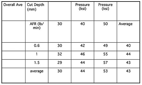
The table is a summary of some of the results and it shows results for a feed that began at 250 microns giving the percentage of the particles that survived at larger than 100 microns.


Figure 8. Percentage of the 250 micron sized feed that survives at above 100 micron for differing jet conditions. (the numbers are averaged from several tests).

It can be seen that when the feed rate rises to 1.5 lb a minute that there is a drop in abrasive size at higher jet pressures, and this is likely to be due to the increased interaction with particles. Since cutting effectiveness is controlled by particle size, count and velocity the only slightly greater amount of particles that survive above 100 microns at 1.5 lb/minute relative to those that survive at 1 lb/minute suggest that spending the money to increase the AFR above the optimal value (in this case around 1 lb/min) is a wasted investment.

It is therefore important to tune the system to ensure that, for each jet pressure and nozzle design that is used, that the AFR has been optimized.

Read more!

Friday, December 6, 2013

Waterjetting 16a - Abrasive Feed

I was talking with someone the other day who mentioned that it was necessary to increase the amount of abrasive feed to a waterjet whenever the material to be cut was thicker. This is actually a myth, or put another way, wrong! It is the equivalent of saying that you should use a duller knife if you want to cut thinner material.

Today’s topic therefore is about optimizing the abrasive feed rate into an abrasive waterjet cutting system, but you should remember that different manufacturers have different nozzle assembly designs. Thus the graphs and tables that I will use to illustrate the discussion relate to one particular nozzle design that was used at that time. Not all the nozzle designs were the same, but the results illustrate the points that I am going to make. But it underlies the recommendation that you should each run some standard tests with your system so that you have a baseline of performance and data to tell you where your system works best.

There are several reasons why different designs produce different cutting results, and I will point out some of them in what follows. To begin, however, consider again the basic elements of the waterjet mixing chamber.


Figure 1. Section through the mixing chamber of a conventional abrasive injection system.

A small high pressure stream of water enters the chamber through the upper nozzle, passes through the chamber, creating a vacuum that pulls abrasive into the chamber, and mixes with that abrasive before the resulting AWJ exits through the focusing tube.

One of the first things to understand is that, in the cutting jet that issues from the tube the actual cutting comes from the abrasive particles. From work that has been carried out at a number of places we know that the higher the velocity of the particles, the greater the damage that they will do on the target.


Figure 2. Relative mass loss when steel balls hit a mild steel plate (after Hutchings, I.M., Winter, R.E., Field, J.E., "Solid Particle Erosion of Metals;The Removal of Surface Material by Spherical Projectiles," Proceedings of the Royal Society, London, Vol. A348, 1976, pp. 379 - 392.)

Discussion in earlier posts pointed out that there are different ways in which waterjets attack ductile and brittle materials. However the relationship between an increase in impact velocity and damage occurs whether the targets are brittle or ductile. In figure 2 the target was a ductile steel, in more brittle material it is the coalescence of cracks that removes material, and higher velocities create larger cracks, as shown in figure 3.


Figure 3. Effect of impact velocity on crack length, (after Evans, A.G., "Impact Damage Mechanics: Solid Projectiles," in Erosion, Treatise on Materials Science and Technology, Vol. 16, ed C. Preece, Academic Press, 1979.).

And the same form holds true if steel balls are fired into sandstone.


Figure 4. Relative amount of Berea sandstone removed by the impact of steel balls of varying size (after Ripkin, J.F., Wetzel, J.M., A Study of the Fragmentation of Rock byImpingement with Water and Solid Impactors, Final Report on U.S. Bureau of Mines, Contract HO 210021, February, 1972.).

The above graphs show that it is more effective to have the abrasive moving faster in terms of the damage done by individual particles. Which brings up the first consideration in the design and use of an AWJ mixing chamber.

In order to get the particles moving as fast as possible they have to get their energy from the water jet entering the chamber. But the jet enters the chamber as a solid stream that then breaks into droplets (as shown in earlier pictures) as it passes down the chamber. If the jet remains in a solid stream all the way down, and out of the focusing tube, then the abrasive will find it difficult to penetrate into the center of the jet stream and pick up all the needed jet energy.

This can be illustrated by looking at the velocity and distribution of particles coming out of a nozzle with two different sizes of waterjet orifice but the same size of focusing tube diameter.


Figure 5. Relative particle distribution across a 40,000 psi jet with a focusing tube diameter of 2.3 mm (0.09 inches), and an AFR of 1 lb/min for two waterjet orifice sizes (after Mazurkiewicz, M., Olko, P., Jordan, R., "Abrasive Particle Distribution in a High Pressure Hydroabrasive Jet," International Water Jet Symposium, Beijing, China, September, 1987, pp. 4-1 - 4-10.)

The smaller waterjet breaks up fully within the chamber entraining and accelerating the abrasive particles and providing the desired cutting stream. The larger sized jet does not completely breakup, and fewer particles can mix into the center of the jet giving a more diffuse and less efficient cutting stream. In this case changing from a 0.005 inch waterjet orifice to a 0.013 inch diameter orifice (at roughly 7 times more power, because of the higher flow rate) produces a poorer result.

It is therefore important to ensure that there is an efficient energy transfer between the water and the particles. But the jet energy can only be diffused to a certain number of particles before it significantly begins to reduce in the amount of energy that it imparts to each particle. In other words if you put too much abrasive into the jet stream, then the amount of energy each particle gets is reduced, as it the overall cutting efficiency.

In an example I have used in class I noted that if I pick up a small child and run down the corridor, then I can carry the child at about my normal running speed, on the other hand if I pick up a couple of football players and try the same run I will be barely able to stagger. So the optimum carrying capacity of any jet can be determined for a given water flow rate, which is itself based on the waterjet orifice diameter and the pressure at which the water is supplied.

I will return to this topic next time, but you can see, in the concluding figure, that when a lower abrasive feed rate is fed to the nozzle, that the percentage of the abrasive moving in the higher velocity range rises to over 60% compared with only 20% of the particles when the abrasive feed is too high. And that means that the cutting performance will be less with the higher abrasive feed rates. (The numbers are a little high to reinforce the point).


Figure 7. Particle velocity distribution on leaving the focusing tube (after Isobe, T., Yoshida, H., Nishi, K., "Distribution of Abrasive Particles in Abrasive Water Jet and Acceleration Mechanism," paper E2, 9th International Symposium on Jet Cutting Technology, Sendai, Japan, Oct, 1988, pp. 217 - 238.)

Read more!

Tuesday, February 19, 2013

Waterjetting 6b - The Triangle comparison test

This post is being written in Missouri, and while the old saying about “I’m from Missouri, you’re going to have to show me,” has a different origin than most folk recognize*, it is a saying that has served well over the years. We did some work once for the Navy, who were concerned that shooting high-pressure waterjets at pieces of explosive might set them off, as we worked to remove the explosive from the casing. We ran tests under a wide range of conditions, and said, in effect, “see it didn’t go off – it’s bound to be safe!” “No,” they replied, “ we need to know what pressure causes it go off at, and then we can calculate the safety factor.” And so we built different devices that fired waterjets at pressure of up to 10 million psi, and at that pressure (and usually a fair bit below it) all the different explosives reacted. And it turned out that one of the pressures that had been tested earlier was not that far below the sensitivity pressure of one of the explosives.

That is, perhaps a little clumsily, a lead in to explain why just getting simple answers, such as “yes I can clean this,” or “yes I can cut that” doesn’t often give the best answer. One can throw a piece of steel, for example, on a cutting table, and cut out a desired shape at a variety of pressures, abrasive feed rates (AFR) and cutting speeds. If the first attempt worked then this might well be the set of cutting conditions that become part of the lore of the shop. After a while it becomes “but we’ve always done it that way,” and the fact that it could be done a lot faster, with a cleaner cut, less abrasive use and at a lower cost is something that rarely gets revisited.

So how does one go about a simple set of tests to find those answers? For many years we worked on cutting steel. Our tests were therefore designed around cutting steel samples, because that gave us the most relevant information, but if your business mainly cuts aluminum, or titanium or some other material then the test design can be modified for that reason.

The test that we use is called a “triangle” test because that is what we use. And because we did a lot of them we bought several strips of 0.25-inch thick, 4-inch wide, ASTM A108 steel so that we would have a consistent target. (Both quarter and three-eighths thick pieces have been used, depending on what was available). The dimensions aren’t that important, though the basic shape that we then cut the strips into has some advantage, as I’ll explain. (It later turned out that we could have used samples only 3-inches wide, but customs die hard, and with higher pressures the original size continues to work).

>br>Figure 1. Basic Triangle Shape

The choice to make the sample 6-inches long is also somewhat arbitrary. We preferred to make a cutting run of about 3 minutes, so that the system was relatively stable, and we had a good distance over which to make measurements, but if you have some scrap pieces that can give several triangular samples of roughly the same shape, then use those.

The sample is then placed in a holder, clamped to a strut in the cutting table, and set so that the 6-inch length is uppermost, and the triangle is pointing downwards.


Figure 2. The holder for the sample triangle.

The nozzle is placed so that it will cut, from the sharp end of the triangle, along the center of the 0.25-inch thickness towards the 4-inch end of the piece. The piece is set with the top of the sample at the level of the water in the cutting table. The piece is then cut – at the pressure, AFR, and at a speed of 1.25 inches per minute, with the cut stopped before it reaches the far end of the piece, though the test should run for at least a minute after the jet has stopped cutting all the way through the sample.

The piece is then removed from the cutting table, and, for a simple comparison the point at which the jet stopped cutting all the way through the triangle is noted.


Figure 3. Showing the point at which the jet stopped cutting through various samples, as a function of the age of the nozzle – all other cutting conditions were the same. (A softer nozzle material was being tested, which is why the lifetime was so short). The view of the samples is from the underside (A in Fig 1.)

An abrasive jet cuts into material in a couple of different ways - the initial smooth section where the primary contact occurs between the jet and the piece, and the rougher lower section where the particles have hit and bounced once on the target, and now widen and roughen the cut. Since some work requires the quality of the first depth, we take the steel samples, and mill one side of the sample, along the lower edge of the cut until the mill reaches the depth of the cut, and then we cut off that flap of material, so that the cut can be exposed. Note that the depth is measured to the top of the section where the depth varies.


Figure 4. Typical example of a steel triangle that has been cut and then sectioned to show the quality of the cut.

I mentioned, in an earlier article, that we had compared different designs from competing manufacturers. Under exactly the same pressure, water flow and abrasive feed rates, the difference between the cutting results differed more greatly than had been expected.


Figure 5. Sectioned views of six samples cut by different nozzle designs, but at the same pressure, water flow, AFR and cutting speed.

There was sufficient difference that we went and bought second, and third copies of different nozzles and tested them to make sure that the results were valid, and they were confirmed with those additional tests. Over the years as other manufacturers produced new designs, these were tested and added into the table – this was the result after the initial number had doubled. (The blue are results from the first nozzle series tests shown above).


Figure 6. Comparative depths of cut using the same pressure and AFR but twelve different commercially available nozzle designs.

There were a number of reasons for the different results, and I will explain some of those reasons as this series continues, but I will close with a simple example from one of the early comparisons that we made. We ran what is known as a factorial test. In other words the pressure was set at one of three levels, and the AFR was set at one of three levels. If each test ran at one of the combination of pressures and AFR values, and each combination was run once then the nine results can be shown in a table.


Figure 7. Depths of cut resulting from cutting at jet pressures of 30,000 to 50,000 psi and AFR of 0.6, 1.0 and 1.5 lb/min.

The results show that there is no benefit from increasing the AFR above 1 lb/minute (and later testing showed that the best AFR for that particular combination of abrasive type, and water orifice and nozzle diameters was 0.8 lb/minute).

Now most of my cutting audience will already know that value, and may well be using it, but remember that these tests were carried out over fifteen years ago, and at that time the ability to save 20% or more of the abrasive cost with no loss in cutting ability was a significant result. Bear also in mind, that it only took 9 tests (cutting time of around 30 minutes) to find that out.

__________________________________________

* The reason that the “I’m from Missouri, you’ll have to show me,” story got started was that a number of miners migrated to Colorado from Missouri. When they reached the Rockies they found that, though the ways of mining were the same, the words that were used were different. (Each mining district has its own slang). Thus they asked to be shown what the Colorado miners meant, before they could understand what the words related to.

Read more!