Showing posts with label nozzle tests. Show all posts
Wednesday, March 5, 2014
Waterjetting 18d - Abrasive considerations
It would be best if, before I ended this short session on abrasive, I mentioned some of the practical constraints that sometimes limit the options for choosing abrasive types. To give a simple example, we were, at one time, demonstrating the ability of a waterjet drill to penetrate limestone. In the demonstration that morning we had used garnet as the abrasive and had made a steady penetration down to about 70-ft but the contracting office on the project did not seem overly impressed. So, after lunch, I suggested that we switch to an aluminum oxide abrasive, since we knew it was more aggressive.
Unfortunately for the afternoon program we were using a DIAjet type of system, where the abrasive is added to the water under pressure just downstream of the nozzle, and upstream of the delivery nozzle. While that worked well with the garnet abrasive (which passed without significant damage through the swivel on the end of the drill) that was not the case with the aluminum oxide. This is a much sharper abrasive and less prone to damage in mixing. As a result once we had the rig back in operation we were immediately struck by the black color of the water coming out of the hole – as the aluminum oxide stripped the inner lining from the hose carrying it to the nozzle. We then watched as, in real time, the pressure gage on the driving pump slowly slid back from the 10 ksi initial pressure to about 2 ksi as the abrasive ate out the orifices of the nozzle. Needless to say, having pretty much destroyed the downstream equipment in about five minutes, the afternoon demonstration was a bit of a disaster.
I also remember the first time that we used steel shot to try and cut through some rock, without giving too much thought to encasing the cutting operation. Those small spheres retained a lot more energy than most particles, and we were dodging the equivalent of shotgun pellets which ricocheted around the lab as we raced to shut the system down.
Both abrasives are, in their place, very effective tools in cutting materials that might be more difficult or uneconomic to cut by other means, but the peculiarities of their nature require that special precautions be used when they are used to make sure that there are not unintended consequences.
Sometimes the choices are simply practical. When we were cutting the walls of the Omnimax theater under the Gateway Arch in St. Louis, where we had to cut straight down (within half-an-inch either way over 15-ft of cut depth) through dolomite and chert it took less than a day to realize that the cost of using garnet to achieve the 12 – 15-inch individual cut depths was going to drive us out of economic reality within a week. Changing to a blasting sand (which we bought by the ton) did not change the cutting performance by much, but had a remarkable effect on overall costs.
Figure 1. Effect of abrasive type, size and feed rate on the depth of cut and optimal cutting condition when cutting rock. (after Yazici*)
Abrasive type and abrasive size both effect the depth of cut, and thus the economics of a cutting operation. Yet it is not possible to draw absolute rules since the different abrasives have different relative cutting efficiencies in different materials. For example, in the above plot boiler slag was relatively ineffective in cutting rock. On the other hand, with the right type of slag and steel Faber and Oweinah** have reported that slag can cut steel more than three times as efficiently as garnet. (This is partly because the slag shatters on impact and the fragments go on to scour the uplifted edges of the cavities generated by the initial impact of the particle.)
And while the British Welding Institute use smaller particles to cut softer materials, they have found it critical to use larger particles to get viable performance as the target material gets harder. In cutting steel I had mentioned in an earlier post, that garnet becomes less effective at a particle size below 100 micron. Yet in cutting aluminum (which is softer) the particles can be smaller and yet still effective.
Figure 2. The effect of particle size when cutting aluminum using corundum particles (after Faber and Oweinah ibid)
Yet, as discussed at the beginning, the cost of the abrasive must not only be set off against the potential for improving the cutting rate, one has to also look and see if there is an increase in the operating cost of the system when a harder, and thus often more effective cutting abrasive is used. Zaring et al showed this with a plot that they published at the 6th American Waterjet Conference***.
Figure 3. Relative benefits and costs of changing abrasive type (after Zaring et al***)
All things are, however, relative, and in some small cutting operations we have found it more economic to sacrifice the nozzle over the cutting time required in order to achieve a cut that could not be effectively achieved any other way.
As with many things in the waterjet business, while there are general rules that can be laid down to guide operations, when it comes to specific cases then it is often worth running a small series of tests on the projected target material, using different abrasives, at varying size ranges and feed rates, before calculating (usually using a normalized cost in dollars or gms per area of cut) the most effective abrasive for a given operation.
*Yazici, Sina, Abrasive Jet Cutting and Drilling of Rock, Ph.D. Dissertation Mining Engineering, Univ. of Missouri- Rolla, Rolla, MO, 1989, 203 pp.
**Faber, K., Oweinah, H., "Influence of Process Parameters on Blasting Performance with the Abrasive Jet," paper 25, 10th International Symp Jet Cutting Technology, Amsterdam, Oct, 1990, pp. 365 - 384.
***Zaring, K., Erichsen, G., Burnham, C., "Procedure Optimization and Hardware Improvements in Abrasive Waterjet Cutting Systems," 6th American Water Jet Conf, Houston, TX, Aug, 1991, pp. 237 - 248.
Unfortunately for the afternoon program we were using a DIAjet type of system, where the abrasive is added to the water under pressure just downstream of the nozzle, and upstream of the delivery nozzle. While that worked well with the garnet abrasive (which passed without significant damage through the swivel on the end of the drill) that was not the case with the aluminum oxide. This is a much sharper abrasive and less prone to damage in mixing. As a result once we had the rig back in operation we were immediately struck by the black color of the water coming out of the hole – as the aluminum oxide stripped the inner lining from the hose carrying it to the nozzle. We then watched as, in real time, the pressure gage on the driving pump slowly slid back from the 10 ksi initial pressure to about 2 ksi as the abrasive ate out the orifices of the nozzle. Needless to say, having pretty much destroyed the downstream equipment in about five minutes, the afternoon demonstration was a bit of a disaster.
I also remember the first time that we used steel shot to try and cut through some rock, without giving too much thought to encasing the cutting operation. Those small spheres retained a lot more energy than most particles, and we were dodging the equivalent of shotgun pellets which ricocheted around the lab as we raced to shut the system down.
Both abrasives are, in their place, very effective tools in cutting materials that might be more difficult or uneconomic to cut by other means, but the peculiarities of their nature require that special precautions be used when they are used to make sure that there are not unintended consequences.
Sometimes the choices are simply practical. When we were cutting the walls of the Omnimax theater under the Gateway Arch in St. Louis, where we had to cut straight down (within half-an-inch either way over 15-ft of cut depth) through dolomite and chert it took less than a day to realize that the cost of using garnet to achieve the 12 – 15-inch individual cut depths was going to drive us out of economic reality within a week. Changing to a blasting sand (which we bought by the ton) did not change the cutting performance by much, but had a remarkable effect on overall costs.
Figure 1. Effect of abrasive type, size and feed rate on the depth of cut and optimal cutting condition when cutting rock. (after Yazici*)
Abrasive type and abrasive size both effect the depth of cut, and thus the economics of a cutting operation. Yet it is not possible to draw absolute rules since the different abrasives have different relative cutting efficiencies in different materials. For example, in the above plot boiler slag was relatively ineffective in cutting rock. On the other hand, with the right type of slag and steel Faber and Oweinah** have reported that slag can cut steel more than three times as efficiently as garnet. (This is partly because the slag shatters on impact and the fragments go on to scour the uplifted edges of the cavities generated by the initial impact of the particle.)
And while the British Welding Institute use smaller particles to cut softer materials, they have found it critical to use larger particles to get viable performance as the target material gets harder. In cutting steel I had mentioned in an earlier post, that garnet becomes less effective at a particle size below 100 micron. Yet in cutting aluminum (which is softer) the particles can be smaller and yet still effective.
Figure 2. The effect of particle size when cutting aluminum using corundum particles (after Faber and Oweinah ibid)
Yet, as discussed at the beginning, the cost of the abrasive must not only be set off against the potential for improving the cutting rate, one has to also look and see if there is an increase in the operating cost of the system when a harder, and thus often more effective cutting abrasive is used. Zaring et al showed this with a plot that they published at the 6th American Waterjet Conference***.
Figure 3. Relative benefits and costs of changing abrasive type (after Zaring et al***)
All things are, however, relative, and in some small cutting operations we have found it more economic to sacrifice the nozzle over the cutting time required in order to achieve a cut that could not be effectively achieved any other way.
As with many things in the waterjet business, while there are general rules that can be laid down to guide operations, when it comes to specific cases then it is often worth running a small series of tests on the projected target material, using different abrasives, at varying size ranges and feed rates, before calculating (usually using a normalized cost in dollars or gms per area of cut) the most effective abrasive for a given operation.
*Yazici, Sina, Abrasive Jet Cutting and Drilling of Rock, Ph.D. Dissertation Mining Engineering, Univ. of Missouri- Rolla, Rolla, MO, 1989, 203 pp.
**Faber, K., Oweinah, H., "Influence of Process Parameters on Blasting Performance with the Abrasive Jet," paper 25, 10th International Symp Jet Cutting Technology, Amsterdam, Oct, 1990, pp. 365 - 384.
***Zaring, K., Erichsen, G., Burnham, C., "Procedure Optimization and Hardware Improvements in Abrasive Waterjet Cutting Systems," 6th American Water Jet Conf, Houston, TX, Aug, 1991, pp. 237 - 248.
Read more!
Monday, March 4, 2013
Waterjetting 6d - Plywood and Pork, and jet effectiveness
In the last two posts I have tried to show that there is a benefit to running an occasional calibration test on equipment, to ensure that it is giving the best performance. This does not mean that the nozzle needs to be tested every day, although some of the cheaper pressure washer nozzles, for example, will wear out in less than an hour. An operator will learn, over time, about how long a nozzle will last, and can, after a while, tell when it is starting to lose performance. But in working on a number of different jobs in succession that sense of the performance may be missed, and it can be handy to have a standard target that a jet can be pointed at that it should be able to cut in a known time.
One simple target is plywood, and, to continue the saga of nozzle comparisons through a slightly different approach, Mike Woodward used plywood sheets to compare different nozzles in one of the earliest comparisons of performance. We since duplicated his test equipment and ran tests with a more modern selection of nozzles, but the basic results and conclusions remain the same.
In its simplest form the idea is to build a holding frame that will hold small squares of plywood at fixed distances from the nozzle. In the frame shown below the plywood pieces are set at one-foot distances apart, with the nozzle held at a fixed point at the end of the test frame. Tests showed that it takes around 2,700 psi to cut through the plywood.

Figure 1. A simple frame to hold plywood samples
The initial tests that Dr. Woodward ran were run on nozzles that were run at 10,000 psi with a nominal flow rate of 10 gpm. The nozzles that were used cost in the range from $10.00 to $250 apiece. (And these costs were reported in 1985 at the 3rd American Waterjet Conference). Tests such as this are simple to run. Plywood pieces are set into the frame, the nozzle is placed at the end of the frame, and the jet run for ten seconds. Over that time, the jet will cut through any of the pieces of plywood that it reaches with enough power to cut through, and generally the jet will punch a hole through several pieces.

Figure 2. The different designs of nozzle that Mike Woodward tested in 1985.
The profiles show that there was only one of the common nozzles at the time that fitted smoothly onto the end of the feed pipe. In the other cases there is a small gap between the nozzle piece and the feed tube, so that turbulence would be generated just as water entered the acceleration section of the nozzle.
The hole size in each plate was then measured, and that width plotted as a function of the distance from the nozzle, so that a profile of the jet cutting path could then be drawn.

Figure 3. Profiles cut into the different pieces of wood, showing the cutting power of the different jets, as a function of distance and the actual amount of water flow as measured.
As an additional part of the testing a rough measure was kept of the effective nozzle life Some other performance parameters for the different nozzles can be put into a table.

Figure 4. Performance of the different nozzles.
Clearly just going out and buying the most expensive nozzle on the block is not necessarily the best idea. But it also depends on the use to which the nozzle is going to be applied. There are two different applications, that of cleaning a surface, and that of cutting into it. The broader path achieved by nozzle 1, for example, which also removed the largest volume of wood per horsepower, makes it a good selection for cleaning, and for reaching further from the nozzle, as would be needed if one were cleaning the pipes of a heat exchanger bundle.
On the other hand the more coherent flow through nozzle 2, which gave a narrower cut might be a more effective tool in a cutting operation. In other cleaning operations where the nozzle is being operated very close to the surface, then nozzle 3, which has a wider path, might be a better choice, though that is lost if the target surface is further away. And though there was not a great deal of difference in performance between nozzles 1 and 5, there is a considerable difference in price.
A smaller, lighter nozzle may be a beneficial trade-off if the nozzle body is fitting on the end of a lance that will be operated manually for several hours at a time.
There is an alternate way of using plywood as a target that I have also used in teaching class. The student is using a manually operated high-pressure cleaning gun at 10,000 psi and is to swing the gun horizontally so that the jet cuts into a piece of plywood that is set almost parallel with the jet path, but with the stream hitting the wood from the side initially further from the operator, but as the swing completes the jet cuts up where the nozzle almost touches it and then sweeps on past.
The result is that, over the distance that the jet can cut into the wood, a groove is carved into the wood.

Figure 5. Horizontal cuts into plywood. There were about half-a-dozen students who had swiped the nozzle so that it just cleared the left edge of this 4-ft wide piece of plywood, and you may note that the cuts extend roughly ¾ of the way along the surface.
Once the students had seen this cut, I would ask them how far away they thought, based on that measurement, that the jet would cut into a person. Typically they said about three feet, and then, as a precaution, I suggested they add a foot or so more.
Then I took them over to a metal frame where we had hung a piece of pork. We carefully measured off the “safe” distance from the end of the nozzle to the pork.
“Now assume that is you”, I would say, “swing the jet as fast as you can, so that it barely has time to hit “your arm”, and we’ll just check that distance is correct.”

Figure 6. Piece of pork that has been traversed by a 10,000 psi jet several times, with a typical standoff distance from the nozzle of more than four feet.
Invariably we got the result shown in Figure 6. The jet would cut into the meat to a typical depth of around two inches and groove the underlying bone. It was a salutary way of getting their attention about the safe use of the tool, and I noticed that the staff also got a bit more cautious after we ran this class every year.
One simple target is plywood, and, to continue the saga of nozzle comparisons through a slightly different approach, Mike Woodward used plywood sheets to compare different nozzles in one of the earliest comparisons of performance. We since duplicated his test equipment and ran tests with a more modern selection of nozzles, but the basic results and conclusions remain the same.
In its simplest form the idea is to build a holding frame that will hold small squares of plywood at fixed distances from the nozzle. In the frame shown below the plywood pieces are set at one-foot distances apart, with the nozzle held at a fixed point at the end of the test frame. Tests showed that it takes around 2,700 psi to cut through the plywood.

Figure 1. A simple frame to hold plywood samples
The initial tests that Dr. Woodward ran were run on nozzles that were run at 10,000 psi with a nominal flow rate of 10 gpm. The nozzles that were used cost in the range from $10.00 to $250 apiece. (And these costs were reported in 1985 at the 3rd American Waterjet Conference). Tests such as this are simple to run. Plywood pieces are set into the frame, the nozzle is placed at the end of the frame, and the jet run for ten seconds. Over that time, the jet will cut through any of the pieces of plywood that it reaches with enough power to cut through, and generally the jet will punch a hole through several pieces.

Figure 2. The different designs of nozzle that Mike Woodward tested in 1985.
The profiles show that there was only one of the common nozzles at the time that fitted smoothly onto the end of the feed pipe. In the other cases there is a small gap between the nozzle piece and the feed tube, so that turbulence would be generated just as water entered the acceleration section of the nozzle.
The hole size in each plate was then measured, and that width plotted as a function of the distance from the nozzle, so that a profile of the jet cutting path could then be drawn.

Figure 3. Profiles cut into the different pieces of wood, showing the cutting power of the different jets, as a function of distance and the actual amount of water flow as measured.
As an additional part of the testing a rough measure was kept of the effective nozzle life Some other performance parameters for the different nozzles can be put into a table.

Figure 4. Performance of the different nozzles.
Clearly just going out and buying the most expensive nozzle on the block is not necessarily the best idea. But it also depends on the use to which the nozzle is going to be applied. There are two different applications, that of cleaning a surface, and that of cutting into it. The broader path achieved by nozzle 1, for example, which also removed the largest volume of wood per horsepower, makes it a good selection for cleaning, and for reaching further from the nozzle, as would be needed if one were cleaning the pipes of a heat exchanger bundle.
On the other hand the more coherent flow through nozzle 2, which gave a narrower cut might be a more effective tool in a cutting operation. In other cleaning operations where the nozzle is being operated very close to the surface, then nozzle 3, which has a wider path, might be a better choice, though that is lost if the target surface is further away. And though there was not a great deal of difference in performance between nozzles 1 and 5, there is a considerable difference in price.
A smaller, lighter nozzle may be a beneficial trade-off if the nozzle body is fitting on the end of a lance that will be operated manually for several hours at a time.
There is an alternate way of using plywood as a target that I have also used in teaching class. The student is using a manually operated high-pressure cleaning gun at 10,000 psi and is to swing the gun horizontally so that the jet cuts into a piece of plywood that is set almost parallel with the jet path, but with the stream hitting the wood from the side initially further from the operator, but as the swing completes the jet cuts up where the nozzle almost touches it and then sweeps on past.
The result is that, over the distance that the jet can cut into the wood, a groove is carved into the wood.

Figure 5. Horizontal cuts into plywood. There were about half-a-dozen students who had swiped the nozzle so that it just cleared the left edge of this 4-ft wide piece of plywood, and you may note that the cuts extend roughly ¾ of the way along the surface.
Once the students had seen this cut, I would ask them how far away they thought, based on that measurement, that the jet would cut into a person. Typically they said about three feet, and then, as a precaution, I suggested they add a foot or so more.
Then I took them over to a metal frame where we had hung a piece of pork. We carefully measured off the “safe” distance from the end of the nozzle to the pork.
“Now assume that is you”, I would say, “swing the jet as fast as you can, so that it barely has time to hit “your arm”, and we’ll just check that distance is correct.”

Figure 6. Piece of pork that has been traversed by a 10,000 psi jet several times, with a typical standoff distance from the nozzle of more than four feet.
Invariably we got the result shown in Figure 6. The jet would cut into the meat to a typical depth of around two inches and groove the underlying bone. It was a salutary way of getting their attention about the safe use of the tool, and I noticed that the staff also got a bit more cautious after we ran this class every year.
Read more!
Labels:
000 psi,
10,
cut depth,
Mike Woodward,
nozzle lifetime,
nozzle tests,
plywood,
pork
Tuesday, February 19, 2013
Waterjetting 6b - The Triangle comparison test
This post is being written in Missouri, and while the old saying about “I’m from Missouri, you’re going to have to show me,” has a different origin than most folk recognize*, it is a saying that has served well over the years. We did some work once for the Navy, who were concerned that shooting high-pressure waterjets at pieces of explosive might set them off, as we worked to remove the explosive from the casing. We ran tests under a wide range of conditions, and said, in effect, “see it didn’t go off – it’s bound to be safe!” “No,” they replied, “ we need to know what pressure causes it go off at, and then we can calculate the safety factor.” And so we built different devices that fired waterjets at pressure of up to 10 million psi, and at that pressure (and usually a fair bit below it) all the different explosives reacted. And it turned out that one of the pressures that had been tested earlier was not that far below the sensitivity pressure of one of the explosives.
That is, perhaps a little clumsily, a lead in to explain why just getting simple answers, such as “yes I can clean this,” or “yes I can cut that” doesn’t often give the best answer. One can throw a piece of steel, for example, on a cutting table, and cut out a desired shape at a variety of pressures, abrasive feed rates (AFR) and cutting speeds. If the first attempt worked then this might well be the set of cutting conditions that become part of the lore of the shop. After a while it becomes “but we’ve always done it that way,” and the fact that it could be done a lot faster, with a cleaner cut, less abrasive use and at a lower cost is something that rarely gets revisited.
So how does one go about a simple set of tests to find those answers? For many years we worked on cutting steel. Our tests were therefore designed around cutting steel samples, because that gave us the most relevant information, but if your business mainly cuts aluminum, or titanium or some other material then the test design can be modified for that reason.
The test that we use is called a “triangle” test because that is what we use. And because we did a lot of them we bought several strips of 0.25-inch thick, 4-inch wide, ASTM A108 steel so that we would have a consistent target. (Both quarter and three-eighths thick pieces have been used, depending on what was available). The dimensions aren’t that important, though the basic shape that we then cut the strips into has some advantage, as I’ll explain. (It later turned out that we could have used samples only 3-inches wide, but customs die hard, and with higher pressures the original size continues to work).
>br>Figure 1. Basic Triangle Shape
The choice to make the sample 6-inches long is also somewhat arbitrary. We preferred to make a cutting run of about 3 minutes, so that the system was relatively stable, and we had a good distance over which to make measurements, but if you have some scrap pieces that can give several triangular samples of roughly the same shape, then use those.
The sample is then placed in a holder, clamped to a strut in the cutting table, and set so that the 6-inch length is uppermost, and the triangle is pointing downwards.

Figure 2. The holder for the sample triangle.
The nozzle is placed so that it will cut, from the sharp end of the triangle, along the center of the 0.25-inch thickness towards the 4-inch end of the piece. The piece is set with the top of the sample at the level of the water in the cutting table. The piece is then cut – at the pressure, AFR, and at a speed of 1.25 inches per minute, with the cut stopped before it reaches the far end of the piece, though the test should run for at least a minute after the jet has stopped cutting all the way through the sample.
The piece is then removed from the cutting table, and, for a simple comparison the point at which the jet stopped cutting all the way through the triangle is noted.

Figure 3. Showing the point at which the jet stopped cutting through various samples, as a function of the age of the nozzle – all other cutting conditions were the same. (A softer nozzle material was being tested, which is why the lifetime was so short). The view of the samples is from the underside (A in Fig 1.)
An abrasive jet cuts into material in a couple of different ways - the initial smooth section where the primary contact occurs between the jet and the piece, and the rougher lower section where the particles have hit and bounced once on the target, and now widen and roughen the cut. Since some work requires the quality of the first depth, we take the steel samples, and mill one side of the sample, along the lower edge of the cut until the mill reaches the depth of the cut, and then we cut off that flap of material, so that the cut can be exposed. Note that the depth is measured to the top of the section where the depth varies.

Figure 4. Typical example of a steel triangle that has been cut and then sectioned to show the quality of the cut.
I mentioned, in an earlier article, that we had compared different designs from competing manufacturers. Under exactly the same pressure, water flow and abrasive feed rates, the difference between the cutting results differed more greatly than had been expected.

Figure 5. Sectioned views of six samples cut by different nozzle designs, but at the same pressure, water flow, AFR and cutting speed.
There was sufficient difference that we went and bought second, and third copies of different nozzles and tested them to make sure that the results were valid, and they were confirmed with those additional tests. Over the years as other manufacturers produced new designs, these were tested and added into the table – this was the result after the initial number had doubled. (The blue are results from the first nozzle series tests shown above).

Figure 6. Comparative depths of cut using the same pressure and AFR but twelve different commercially available nozzle designs.
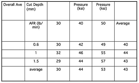
There were a number of reasons for the different results, and I will explain some of those reasons as this series continues, but I will close with a simple example from one of the early comparisons that we made. We ran what is known as a factorial test. In other words the pressure was set at one of three levels, and the AFR was set at one of three levels. If each test ran at one of the combination of pressures and AFR values, and each combination was run once then the nine results can be shown in a table.

Figure 7. Depths of cut resulting from cutting at jet pressures of 30,000 to 50,000 psi and AFR of 0.6, 1.0 and 1.5 lb/min.
The results show that there is no benefit from increasing the AFR above 1 lb/minute (and later testing showed that the best AFR for that particular combination of abrasive type, and water orifice and nozzle diameters was 0.8 lb/minute).
Now most of my cutting audience will already know that value, and may well be using it, but remember that these tests were carried out over fifteen years ago, and at that time the ability to save 20% or more of the abrasive cost with no loss in cutting ability was a significant result. Bear also in mind, that it only took 9 tests (cutting time of around 30 minutes) to find that out.
__________________________________________
* The reason that the “I’m from Missouri, you’ll have to show me,” story got started was that a number of miners migrated to Colorado from Missouri. When they reached the Rockies they found that, though the ways of mining were the same, the words that were used were different. (Each mining district has its own slang). Thus they asked to be shown what the Colorado miners meant, before they could understand what the words related to.
That is, perhaps a little clumsily, a lead in to explain why just getting simple answers, such as “yes I can clean this,” or “yes I can cut that” doesn’t often give the best answer. One can throw a piece of steel, for example, on a cutting table, and cut out a desired shape at a variety of pressures, abrasive feed rates (AFR) and cutting speeds. If the first attempt worked then this might well be the set of cutting conditions that become part of the lore of the shop. After a while it becomes “but we’ve always done it that way,” and the fact that it could be done a lot faster, with a cleaner cut, less abrasive use and at a lower cost is something that rarely gets revisited.
So how does one go about a simple set of tests to find those answers? For many years we worked on cutting steel. Our tests were therefore designed around cutting steel samples, because that gave us the most relevant information, but if your business mainly cuts aluminum, or titanium or some other material then the test design can be modified for that reason.
The test that we use is called a “triangle” test because that is what we use. And because we did a lot of them we bought several strips of 0.25-inch thick, 4-inch wide, ASTM A108 steel so that we would have a consistent target. (Both quarter and three-eighths thick pieces have been used, depending on what was available). The dimensions aren’t that important, though the basic shape that we then cut the strips into has some advantage, as I’ll explain. (It later turned out that we could have used samples only 3-inches wide, but customs die hard, and with higher pressures the original size continues to work).
>br>Figure 1. Basic Triangle Shape
The choice to make the sample 6-inches long is also somewhat arbitrary. We preferred to make a cutting run of about 3 minutes, so that the system was relatively stable, and we had a good distance over which to make measurements, but if you have some scrap pieces that can give several triangular samples of roughly the same shape, then use those.
The sample is then placed in a holder, clamped to a strut in the cutting table, and set so that the 6-inch length is uppermost, and the triangle is pointing downwards.

Figure 2. The holder for the sample triangle.
The nozzle is placed so that it will cut, from the sharp end of the triangle, along the center of the 0.25-inch thickness towards the 4-inch end of the piece. The piece is set with the top of the sample at the level of the water in the cutting table. The piece is then cut – at the pressure, AFR, and at a speed of 1.25 inches per minute, with the cut stopped before it reaches the far end of the piece, though the test should run for at least a minute after the jet has stopped cutting all the way through the sample.
The piece is then removed from the cutting table, and, for a simple comparison the point at which the jet stopped cutting all the way through the triangle is noted.

Figure 3. Showing the point at which the jet stopped cutting through various samples, as a function of the age of the nozzle – all other cutting conditions were the same. (A softer nozzle material was being tested, which is why the lifetime was so short). The view of the samples is from the underside (A in Fig 1.)
An abrasive jet cuts into material in a couple of different ways - the initial smooth section where the primary contact occurs between the jet and the piece, and the rougher lower section where the particles have hit and bounced once on the target, and now widen and roughen the cut. Since some work requires the quality of the first depth, we take the steel samples, and mill one side of the sample, along the lower edge of the cut until the mill reaches the depth of the cut, and then we cut off that flap of material, so that the cut can be exposed. Note that the depth is measured to the top of the section where the depth varies.

Figure 4. Typical example of a steel triangle that has been cut and then sectioned to show the quality of the cut.
I mentioned, in an earlier article, that we had compared different designs from competing manufacturers. Under exactly the same pressure, water flow and abrasive feed rates, the difference between the cutting results differed more greatly than had been expected.

Figure 5. Sectioned views of six samples cut by different nozzle designs, but at the same pressure, water flow, AFR and cutting speed.
There was sufficient difference that we went and bought second, and third copies of different nozzles and tested them to make sure that the results were valid, and they were confirmed with those additional tests. Over the years as other manufacturers produced new designs, these were tested and added into the table – this was the result after the initial number had doubled. (The blue are results from the first nozzle series tests shown above).

Figure 6. Comparative depths of cut using the same pressure and AFR but twelve different commercially available nozzle designs.
There were a number of reasons for the different results, and I will explain some of those reasons as this series continues, but I will close with a simple example from one of the early comparisons that we made. We ran what is known as a factorial test. In other words the pressure was set at one of three levels, and the AFR was set at one of three levels. If each test ran at one of the combination of pressures and AFR values, and each combination was run once then the nine results can be shown in a table.

Figure 7. Depths of cut resulting from cutting at jet pressures of 30,000 to 50,000 psi and AFR of 0.6, 1.0 and 1.5 lb/min.
The results show that there is no benefit from increasing the AFR above 1 lb/minute (and later testing showed that the best AFR for that particular combination of abrasive type, and water orifice and nozzle diameters was 0.8 lb/minute).
Now most of my cutting audience will already know that value, and may well be using it, but remember that these tests were carried out over fifteen years ago, and at that time the ability to save 20% or more of the abrasive cost with no loss in cutting ability was a significant result. Bear also in mind, that it only took 9 tests (cutting time of around 30 minutes) to find that out.
__________________________________________
* The reason that the “I’m from Missouri, you’ll have to show me,” story got started was that a number of miners migrated to Colorado from Missouri. When they reached the Rockies they found that, though the ways of mining were the same, the words that were used were different. (Each mining district has its own slang). Thus they asked to be shown what the Colorado miners meant, before they could understand what the words related to.
Read more!
Wednesday, February 13, 2013
Waterjetting 6a - An introduction to testing nozzle performance
In the next few posts I will be writing about some of the tests that you can run to see how a nozzle is performing. But before getting into the details of the different tests, you should recognize that this is where a little homework will be required if you are to get the most benefit from the topic.
The world that encompasses waterjet use has grown beyond the simple categories by which we used to define it. New techniques make it possible to cut materials that used to be more difficult and expensive to produce, and as practical operational pressures have increased so the scale, precision and economics of new opportunities have developed.
It is this range of application that makes it impractical for me to give specific advice for every situation, and instead, by explaining how to make comparisons, and what some benchmarks might be, to allow you to better understand your system, its capabilities and both the initial performance of nozzles, and then the evaluation to decide when they may best be replaced.
One lesson I learned early was that nozzles from different companies behaved in different ways, and that drawing conclusions on optimal performance, for example the selection for which pressure level and nozzle size was best, using one design would not necessarily hold with a competing design. Further there were nozzles that began their life on our system doing very well relative to others, but which quickly declined in performance. Thus, as part of an evaluation of different designs, we would test the nozzle cutting performance, against a standard requirement, at fixed time intervals so that we would know when it was wearing out and should be replaced.

Figure 1. Change in the cutting depth of a jet stream, at 50,000 psi, when traversed over ASTM A108 steel as a function of the time that the nozzle had been in use.
Both the shape of the curve and the effective lifetimes of different competing nozzle designs varied quite significantly. And obviously, since most folk don’t spend a lot of their time cutting through more than an inch of steel, the operational lifetimes of nozzles will vary with the requirements for the particular job. Nevertheless the relative ages at which nozzles can no longer reach that target can differ significantly,

Figure 2. Comparative effective nozzle life over which, operated at a pressure of 50,000 psi, a jet could cleanly cut a path through a 1.4 inch thick steel target at a traverse rate of 1.5 inches/minute.
As mentioned, the tests were carried out using nozzles from several manufacturers and, at the beginning of the test the longest lasting nozzle was not necessarily the one that produced the fastest cut, but consistently, over the interval, and for about twice as long as the competition, it was able to achieve the goal.

Figure 3. Depths of cut in steel after (top) 1,000 minutes of nozzle use, and (bottom) after 1,500 minutes of nozzle use.
In the particular case in which we made the comparison the major interest was in achieving a clean separation of the parts, and the edge quality was not as significant a factor. In many uses of this tool that edge quality will be important and would have given a different set of numbers (as Figure 3 would indicate) than the ones that were found for our application. As a result the judgment that the nozzle is worn out will change to a different time, and the relative ranking of the different nozzle designs may also change.
The only way in which anyone can make a rational decision on which is the best nozzle for an application, and how long it will be effective is by testing the nozzle against the stated requirement. When we began the test we anticipated that the difference between nozzles from different manufacturers, when fed with water at the same flow rate, and with the same quantity and quality of abrasive would not differ that much. As Figure 2 shows, we were wrong in that idea.
There are a number of different impacts that a change in nozzle design (i.e. in most cases buying a competing design over that initially used) can bring to a cutting operation. However these impacts are also governed by the pressure at which the work is being carried out, the amount of abrasive that is used, the relative nozzle diameters (if using a conventional abrasive waterjet system) and the speed at which the cut is made. But an initial assessment of relative merit should be carried out with equivalent parameters for the different designs.
In general, however, we ran tests at a number of pressures, and with varying abrasive feed rates, to ensure that the comparative evaluations were fair, and consistent. As a result we found that there were a number of different factors that came into play, which are not always recognized, and which could bias the results that we observed.
In the posts that follow this I will first cover some of the different tests that can be used, and then go on to explain some of the results and why they sometimes make it difficult to accept a simple comparison of results when, for example, the abrasive is not the same in both cases. To give a simple example of this, consider a conventional abrasive waterjet nozzle that is operated at increasing pressure.
Increasing the pressure will improve the cutting speed and/or the cut quality, as a general rule. It will reduce the amount of abrasive that is needed, but this is where the “yes, but’s . . . .” start to appear. As the pressure of the jet increases, so the amount of abrasive that is broken within the mixing chamber will also increase, so that the average size of the particle coming out of the nozzle will become smaller. The amount of this size reduction is a function of the quality of the abrasive that is being used, and a function of the initial size of that abrasive.
Within a certain size range, that reduction in the particle size does not significantly change the cutting performance, but if the mix contains too many small particles, particularly if the distance to the work piece is also significant, then the cutting performance can be reduced because of the particle break-up. Different nozzle designs produce different amounts of very fine material even from the same feed rate of the same abrasive into the nozzle. When the initial feed rate of the abrasive, or a different abrasive is used, then estimating which design and set of operating pressures is best becomes more difficult, as an abstract estimation.
This is why, in the posts that follow, the comparisons are made are based on actual measurements and why I recommend that everyone test their system using more than one design/set of operating parameters so that they can be confident that the combination that they are using will provide the best combination for the job to be done.
The world that encompasses waterjet use has grown beyond the simple categories by which we used to define it. New techniques make it possible to cut materials that used to be more difficult and expensive to produce, and as practical operational pressures have increased so the scale, precision and economics of new opportunities have developed.
It is this range of application that makes it impractical for me to give specific advice for every situation, and instead, by explaining how to make comparisons, and what some benchmarks might be, to allow you to better understand your system, its capabilities and both the initial performance of nozzles, and then the evaluation to decide when they may best be replaced.
One lesson I learned early was that nozzles from different companies behaved in different ways, and that drawing conclusions on optimal performance, for example the selection for which pressure level and nozzle size was best, using one design would not necessarily hold with a competing design. Further there were nozzles that began their life on our system doing very well relative to others, but which quickly declined in performance. Thus, as part of an evaluation of different designs, we would test the nozzle cutting performance, against a standard requirement, at fixed time intervals so that we would know when it was wearing out and should be replaced.

Figure 1. Change in the cutting depth of a jet stream, at 50,000 psi, when traversed over ASTM A108 steel as a function of the time that the nozzle had been in use.
Both the shape of the curve and the effective lifetimes of different competing nozzle designs varied quite significantly. And obviously, since most folk don’t spend a lot of their time cutting through more than an inch of steel, the operational lifetimes of nozzles will vary with the requirements for the particular job. Nevertheless the relative ages at which nozzles can no longer reach that target can differ significantly,

Figure 2. Comparative effective nozzle life over which, operated at a pressure of 50,000 psi, a jet could cleanly cut a path through a 1.4 inch thick steel target at a traverse rate of 1.5 inches/minute.
As mentioned, the tests were carried out using nozzles from several manufacturers and, at the beginning of the test the longest lasting nozzle was not necessarily the one that produced the fastest cut, but consistently, over the interval, and for about twice as long as the competition, it was able to achieve the goal.

Figure 3. Depths of cut in steel after (top) 1,000 minutes of nozzle use, and (bottom) after 1,500 minutes of nozzle use.
In the particular case in which we made the comparison the major interest was in achieving a clean separation of the parts, and the edge quality was not as significant a factor. In many uses of this tool that edge quality will be important and would have given a different set of numbers (as Figure 3 would indicate) than the ones that were found for our application. As a result the judgment that the nozzle is worn out will change to a different time, and the relative ranking of the different nozzle designs may also change.
The only way in which anyone can make a rational decision on which is the best nozzle for an application, and how long it will be effective is by testing the nozzle against the stated requirement. When we began the test we anticipated that the difference between nozzles from different manufacturers, when fed with water at the same flow rate, and with the same quantity and quality of abrasive would not differ that much. As Figure 2 shows, we were wrong in that idea.
There are a number of different impacts that a change in nozzle design (i.e. in most cases buying a competing design over that initially used) can bring to a cutting operation. However these impacts are also governed by the pressure at which the work is being carried out, the amount of abrasive that is used, the relative nozzle diameters (if using a conventional abrasive waterjet system) and the speed at which the cut is made. But an initial assessment of relative merit should be carried out with equivalent parameters for the different designs.
In general, however, we ran tests at a number of pressures, and with varying abrasive feed rates, to ensure that the comparative evaluations were fair, and consistent. As a result we found that there were a number of different factors that came into play, which are not always recognized, and which could bias the results that we observed.
In the posts that follow this I will first cover some of the different tests that can be used, and then go on to explain some of the results and why they sometimes make it difficult to accept a simple comparison of results when, for example, the abrasive is not the same in both cases. To give a simple example of this, consider a conventional abrasive waterjet nozzle that is operated at increasing pressure.
Increasing the pressure will improve the cutting speed and/or the cut quality, as a general rule. It will reduce the amount of abrasive that is needed, but this is where the “yes, but’s . . . .” start to appear. As the pressure of the jet increases, so the amount of abrasive that is broken within the mixing chamber will also increase, so that the average size of the particle coming out of the nozzle will become smaller. The amount of this size reduction is a function of the quality of the abrasive that is being used, and a function of the initial size of that abrasive.
Within a certain size range, that reduction in the particle size does not significantly change the cutting performance, but if the mix contains too many small particles, particularly if the distance to the work piece is also significant, then the cutting performance can be reduced because of the particle break-up. Different nozzle designs produce different amounts of very fine material even from the same feed rate of the same abrasive into the nozzle. When the initial feed rate of the abrasive, or a different abrasive is used, then estimating which design and set of operating pressures is best becomes more difficult, as an abstract estimation.
This is why, in the posts that follow, the comparisons are made are based on actual measurements and why I recommend that everyone test their system using more than one design/set of operating parameters so that they can be confident that the combination that they are using will provide the best combination for the job to be done.
Read more!
Subscribe to:
Posts (Atom)