Showing posts with label geothermal wells. Show all posts

Monday, November 10, 2014

Tech Talk - Geothermal Plant Opens

The Missouri University of Science & Technology Geothermal system was officially opened last Thursday, some months after the coal and wood fired power plant that had previously warmed the campus had been shut down.


Figure 1. Chancellor Schrader cutting the ribbon to officially open the system.

The operation ended up being a little larger than originally anticipated, although the receipt of several grants kept the need for external funding bonds down to $30 million. Overall, as the old heating and cooling system was replaced around campus, deferred maintenance costs of some $60 million disappeared as the new system eliminated those needs, and is anticipated to generate fuel overall savings of some $1 million initially rising to $2.8 million a year as future fuel prices rise over the years.

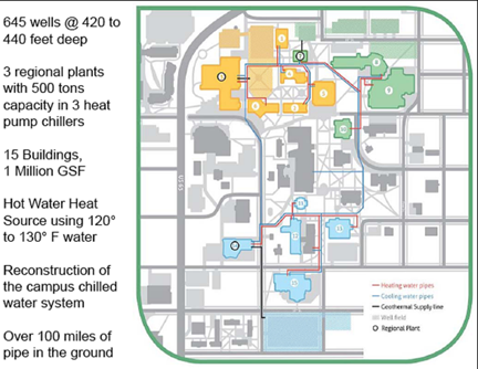
In the end some 645 wells were drilled to feed three different geothermal plants located around the campus. Well depths ranged from 420 to 440 ft., and with a background temperature around the wells averaging around 60 deg F.

The installed system is, to a large extent, computer controlled, so that it was necessary to find employment for the fifteen workers at the power plant who would otherwise have been laid off. Given that some took retirement, the University was able to absorb the rest into the workforce in various ways. But it does point out that, now that the system is installed, the number of jobs associated with this new sustainable energy system are significantly below that required at the power plant, and the coal mine and forestry products supplier that previously supplied the fuel. Maintenance of the system, which is largely built around pumps, pipes and valves can, in the main, be carried out by the normal trades staff at the campus.


Figure 2. Overview board for the individual geothermal flow loops

To illustrate the degree of control that the new system exerts on the Heating and Air Conditioning (HAC) network, consider a simplified circuit for one building.


Figure 3. Illustrated circuit for a single building

Hot water is fed into the building from the network (top left) at a temperature of 118.7 degF, and is mixed with a portion of the previously circulated fluid to give a starting temperature of 113.6 degF entering the building. (The values are in the small boxes over the sensing valve emulations). The hot water circulates around the building providing heat as needed. At the point where the water would exit back to the network for reheating the temperature of the returning water is measured (in this case 102.3 degF). Depending on that temperature a control valve opens or closes to send more (or less) water back for reheating, while the remainder stays in the circuit, with make-up from the main network. (with the valve 41.3% open some 3% of the returning water is being recycled). The computer also calculates the heating load being fed to the building (327.5 kBtu/hr).


Figure 4. Details of the control valve and instrumented values.

By using a similar circuit for cooling the components of the system are largely similar, reducing the inventory costs for maintenance supplies, and the two circuits are simply monitored through instrumentation around the circuit.

This is similarly true for the three geothermal plants, the status of each of which is also represented by a monitoring screen.


Figure 5. Control circuit monitoring the performance of the heat exchangers between the field circulation water and that being used in the building circuit.

The heat exchanges between the ground water and the heating/cooling circuits is through use of three screw type heat recovery chillers, the operation of which is described as:
A heat recovery chiller operates on the basis of a refrigeration cycle: the same basic cycle that is used for refrigerators, air conditioners, and heat pumps you find in your homes. It is designed to provide both useful cooling and useful heating energy from the machine. The work or energy put into the machine through the compressor is used to simply transfer heat from evaporator to the condenser, which makes it a more efficient use of energy than combusting fuel for heat.

As seen in the diagram below, the refrigerate, R-134a in our chiller, is first compressed using a screw-type compressor. This hot gas is then condensed to a liquid as it travels in a circuit through the condenser, and heat is transferred to the water flowing through the condenser tube bundle. The pressure and temperature of the refrigerant is reduced as it flows through the throttling valve. The refrigerant next passes through the evaporator where heat is transferred from the water flowing through the evaporator tube bundle back to the refrigerant. Then the cycle repeats as the refrigerant goes back to the compressor. The refrigerant is confined inside of the heat pump chiller for the entire process.

Figure 6. Operation of the heat exchanger.


Figure 7. Overview of the three chiller units in the McNutt plant

Manually readable gages provide back-up to the computer monitoring instruments.


Figure 8. Monitoring gages for the chilled water loop.

When additional heat is needed, this is provided by a bank of natural gas heaters for the water that can be engaged as needed, and that are similarly monitored.


Figure 9. Overall monitoring board for the natural gas boiler system

While the system may get an early test of effectiveness this week as a Polar Vortex brings an early taste of winter to town, with temperatures predicted to drop to a high of 34 and a low of 19 on Thursday.


Figure 10. Natural gas boiler to provide additional heat as needed.

Since I won't be able to take advantage of those boilers, I’m glad I have my wood stacked, and that I swept my chimney this morning.

Read more!

Monday, May 19, 2014

Tech Talk - Closing a coal-fired power plant

Much is made of large schemes to alter the way in which energy is produced in the United States. Large scale wind farms, and great arrays of solar panels attract large interest and funding, yet it is often in the smaller projects, from the individual solar panels to the change in energy sources for individual factories, or in this case a university, that there is at least as much progress, though with less fanfare.

I wrote, some eighteen months ago about the geothermal plans at Missouri University of Science and Technology (MS&T) previously the University of Missouri-Rolla and my academic home for 42 years. At that time the campus was beginning a process that would see the different parking lots and other open areas around campus disrupted while a series of vertical wells and horizontal pipes was laid beneath the ground, prior to its restoration.


Figure 1. The MS&T Geothermal plan, showing the zoning of the wells and the connection pipe network.

Time has moved on since the initial plans were set in place, the trenches have been dug:


Figure 2. Geothermal trenches on campus, with walkways re-routed around them

Within the lots wells were then drilled roughly 430 ft deep, through which the system fluid will flow, and as these were drilled they were lined and connected by a secondary network.


Figure 3. Drilling the wells in the parking lots at the top right of Figure 1.

The network of wells is connected through plastic pipes that carry the water out to the wells, down and back up and then return to the central heat exchanger systems of the different circuits.


Figure 4. The heat exchange between the water and the ground (inhabitant )


Figure 5. The initial connections to the wells

Larger pipes are required to carry the water to and from the different fields to the processing plants where it is used to heat/chill water in a secondary circuit that is then distributed (depending on season to either warm or cool) through the network to the campus buildings.

Figure 6. The main pipe connections.

The parking lots have since been regraded, tarmac applied, and have, for some time been functioning as before.

Now the project is entering into the final days of installation, as a significant milestone has been reached. This week the coal and wood fired boiler #5 will shut down and all steam production at the campus power plant will permanently cease. Chillers are now operating for the summer to cool the buildings served by three of the regional plantsm which covers most of the air conditioning needs of the campus, and heat is being sent to six of the campus buildings.

Given the age, and change in the nature of the heating and air conditioning service to the buildings some still remain to have their systems upgraded, but most will now be completed while the students are away this summer.

Estimates of the savings that this will bring to the campus are in various forms. The coal and wood that have provided the energy source in the past will no longer be needed (and in time the plant will be removed). As well as the plant itself this will also free up the space where the coal was stored, and will improve the local aesthetic considerably along that side of the campus.


Figure 7. The campus power plant

The change in fuel will also see the overall amount of fuel required reduced, and it is anticipated that the energy use will be cut by 50%. Carbon dioxide emissions will be dropped by 25,000 tons a year (the system will still use significant amounts of natural gas) and water use will be cut by eight million gallons a year.

It is anticipated that the $32 million project will initially yield the campus a saving of around $1 million a year which will rise to more than $3 million a year as energy costs increase, while the system should not need significant maintenance for decades. There is a video of the project here). When completed, sometime next year the system will be serving 15 buildings with around a million square feet of floor space.

As the Missouri system was beginning, the initial phase of a similar system at Ball State was being completed . This will ultimately supply around 5.5 million square feet of campus space, and is expected to yield some $2 million a year in energy cost savings. Following the successful completion of Phase 1 of that project in March 2012, the Phase 2 project, requiring an additional 1,000 boreholes, was started in June of 2013, and is expected to be completed by some time next year. The four coal fired boilers at the plant (which consumed some 36,000 tons of coal a year,) were shut down in March of this year. Power will continue to be supplied from three natural gas boilers on campus. The $80 million project will have drilled a total of around 3,600 wells at the time of completion of Phase 2.

Oregon Tech has a 1.75 MW geothermal power plant, which combined with a solar electric array of panels on a 9-acre site off campus to produce most of the power needs of the campus. The dedication ceremony was on April 18th of this year. It is expected that the plant, which operates on a more conventional use of high-temperature water from the underlying host rock, will save the campus around $400,000 a year in energy. Water is brought up from 5,300 ft below the surface at a temperature of 200 degrees F, and used to spin two turbines, and as source of building heat, before being re-injected.

As the dates suggest this is a very new venture for universities and, as yet, there are not a lot of players in the game. Yet if the savings pan out to be at the level or greater than currently estimated it may well be more popular in the future as overall energy costs continue to rise. (Although in the short term natural gas prices may well rise a little, while coal prices are expected to fall a little).

Read more!