Showing posts with label wilfey table. Show all posts

Tuesday, November 17, 2015

Waterjetting 37e - Using Cavitation to disintegrate rock

In most mines the main objective is to recover as much of the valuable minerals contained within the host (or gangue rock) while minimizing cost. When miners have to go underground and haul the ore to the surface before the minerals are recovered then there is a considerable expense both in hauling all the rock, including the large otherwise valueless host rock, to the surface, and then crushing it to a small size so as to liberate and separate the valuable components.

The work at MS&T, for a number of years, has looked at ways in which rock can be disintegrated, as it is mined, so that the different components are separated as they are freed from the vein. While this work has progressed significantly since it started, this video (of poor quality for which I apologize, but it was what was available at the time) describes where we started the work.


Figure 1. Tom Fort explains the work on cavitation disintegration of rock

  The work was carried on in a number of ways after that, some of which has been described in an earlier post.

Perhaps most relevant to the video at the top of the piece, we were able to develop a more continuous mining process where the material would be mined from the solid in the mine, rather with small hand samples in the lab. While the technology could be easily developed from existing machines now used for hydro-demolition, a more telling picture is to show, by running the product from a test on a sample of dolomite hosting a vein of galena, where the product was run over a Wilfey table.

Figure 2. Mined sample run on a Wilfey table.

The result shows that clear fragmentation of the galena particles and their liberation so that they form a separate (silver) stream on the table from the darker dolomite particles that lie closer to the riffles. It is not quite as easy to see the larger particles of galena which were also separated, but would be more easily recovered perhaps with a screen, since they are not quite as easily streamed from the dolomite.

Read more!

Monday, December 22, 2014

Waterjetting 28b - More on abrasive use

The costs of running a high pressure waterjet table divide into two parts, one that covers the basic costs of the system, whether it is running or not, such as building rent, while the second covers those costs that are a part of the actual work. Of the latter costs it is the cost of the abrasive that is often the most significant. This comes about in two ways, since the abrasive must first be purchased for use, and then, after it has been used it must be disposed of. Depending on the materials that were cut, this disposal cost can be significantly higher than the original purchase price. In some work carried out at the High Pressure Waterjet Lab (HPWL) at Missouri University of Science and Technology (MST) in the past we have seen disposal costs that were more than three times the cost of the original abrasive. And one should bear in mind that, as a research lab, the table was used much less than a comparable conventional table in an industrial cutting environment. But we also did not have a cutting operational budget, and so the cost of abrasive was something that we examined, to see if it could be reduced.

The first idea was that we would just recycle the abrasive. The particles of the target materials that were cut are generally much smaller than the abrasive particles themselves, and so it should be relatively easy to remove them from the mix. However, as we looked into the process in more detail, it was clear that it would not be quite as simple as it might, at first, appear. Marian Mazurkiewicz (retired) and Greg Galecki (who now runs the HPWL) carried out studies on the behavior of the particles as they moved through the mixing chamber and were accelerated down onto the target material. They found, as noted in an earlier post, that most of the abrasive was crushed to a smaller size when it passed through the cutting head, and a mix that started out with a particle size of 210 microns as it was fed into the system, was leaving the focusing tube with an average size of 140 microns.


Figure 1. Percentage of abrasive at different sizes after it has passed through a mixing chamber (and before it has hit the target). (After Galecki).

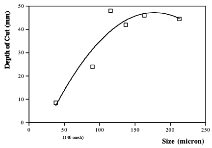
The reason that this is a concern is that, as the particles become smaller, so a point is reached where, depending on the target material, the abrasive no longer has sufficient energy to effectively cut into the target. When cutting into metals such as titanium and steel, our targets of choice in the study, this cut-off grade was at around 100 microns.


Figure 2. Effect of particle size on the cutting performance of an abrasive jet in cutting steel. (The tests were part of a factorial experiment and are thus averages over a number of different test runs at differing abrasive feed rates (AFR and pressures).

Roughly 25% of the mix in the example shown in figure 1 lies below 100 micron at it leaves the chamber. After impacting the target this value increases to more than 50%. Obviously recycling this fine material and re-using it in the cutting process is going to be less effective than removing it from the mix. Generally alluvial garnets will break up more rapidly than mined garnet, because of the structure of the abrasive particles, and thus the percentage that leave the focusing tube at the larger and more effective diameters are lower with the alluvial mix. The results were, we found, confirmed in the cutting results, with alluvial garnet producing a generally shallower depth of cut that would be achieved, other things being equal, in the cutting tests.

A quick word of explanation of the tests we ran, which are described in more detail here. The tests are run at a standard pressure and nozzle size, and at a constant traverse rate, with the depth that the jet cuts into a standard steel at a fixed speed measured over a 4-inch traverse length.

The results of the tests showed that, because of the particle crushing during the cutting process, the abrasive would have to be screened, and for most effective re-use only the larger fraction (on average less than 40%) should be recycled. The rest would be too fine for effective re-use in the operations we were developing. (Although finer abrasive has use in other applications, it would have to be screened and stored). It was interesting to note, and perhaps logical in retrospect, that once the particles had been used once and the larger ones separated out, then the percentage that survived and could be reused a second and third time increased significantly. This is mainly because those particles that had some form of weakness crack (either from weathering or from the mining process) were broken during the first impact, and the particles that survived did not have these cracks, and would therefore inherently be more prone to survive multiple times.

For our purpose, therefore, given that there was a high cost in purchasing the abrasive, and an even higher one in disposing of the contaminated material after cutting (because of the contamination by the target material) there was a potential economic advantage in recycling the abrasive. There were several ways in which the particles can be separated, but a simple screening process, if carried out properly, is quite time consuming, since the particles are required to “sit” on a vibrating screen for several minutes to ensure accurate separation, and this can be labor intensive if it is carried out as a batch process. We tried a number of different ways, including using a counter-flow fluid column that worked well for low feed rates, but the most efficient unit for one operation (we build virtually all of ours, and extensively modified them over time) may not be the best in other cases. (The one that survived the longest was a Wilfey table (though not this one).

In conventional AWJ cutting the abrasive has also to be dried before it can be re-used, and that can also add power and labor costs to the process. Thus, as with many choices that must be made when developing an efficient cutting operation, the best answer is to carry out a series of tests yourself, and run the numbers to decide whether, in the long run, recycling would, or would not, be an effective choice.

Read more!

Monday, February 14, 2011

Gold Rush Alaska - a gentle cough about shaker tables

I do not normally yell at my TV, nor usually want to throw things at it. However I almost reached that point of reaction on Sunday. I had been told about the show “Gold Rush – Alaska” by a couple of folks in my old Department, including a graduate advisee, but had not thought to go and look for it. But setting up to exercise I ran through the channels and an episode had just started. So I watched it as I worked out. (And it did get me more exercised than usual). In this particular episode they were having problems with their Wave table. (Which looks as though it works in a similar way to a table of similar appearance called a Wilfey table, and which I have recently used, as I will show in a photo added to the bottom of this post).

It became very clear, early in the episode, that the folks running it had no clue as to what it was supposed to do, and after a demonstration (which I am not sure wasn’t faked for the camera) where it failed to separate gold from the material run through it, the table was shut down. So I want to explain in very simple detail how the table is supposed to work, and show a photo, albeit with lead rather than gold ore – but that was what we were looking at when I last ran it). This is not rocket science.


The table starts out as a flat surface, onto which a number of thin strips of wood are attached. (Modern ones are of molded plastic ) The strips taper a little as they move along the table. The table is mounted so that it can be tilted in two dimensions, what I will call down the table, and along the table. And for the explanation I am going to use sketches initially.

Schematic of the basic components of a Wifley table.

The crushed ore feeds onto the table in a slurry and water sprays along the top edge of the table are set to give enough fluid to allow the vibration of the table (caused by some sort of eccentric cam resting on the underside) to provide a partial buoyancy to the particles, as well as helping with separation. The combined action of the water flow and the vibration help to move the crushed material both down and along the table, until it hits the top bar (or riffle).

The vibrating action helps to lift the lighter and smaller particles so that they float over this riffle, but the denser valuable particles are not lifted enough. (Remember Archimedes) Instead these then move along the feed edge surface of the riffle and table. If the riffles are of reducing height along the table this means that at some point intermediate weight ores can be separated from the lightest, (which run almost straight down the table) since although initially confined they can lift over a lower barrier. They are also separated from the heaviest ore (gold or lead), which remains confined by the riffles and thus runs down the far end of the table. Smaller particles of the heavier material that get over the top riffle do not have as much water on the lower riffles, and thus become trapped and fed over to the collection stream at the end of the riffles, but lower down the table.


The adjustments to the table are made so that the slope is enough, and the water flow enough, so that the mineral to be collected does not have enough buoyancy from the water and table action to get over all the riffles. It therefore collects at the far end, while the waste material is carried over the riffles then down and off the table. If the table is tilted too steeply, or the flow of water is too high, then even the heaviest particles will be swept over the riffles. (Which was one of the things they wre doing wrong). On the other hand, as is noted below, gold is not a rich ore and so there will be a lot of material swept over the table for very few ounces of recovery.

That is the basic principle, and by more careful adjustment it is possible to separate a mixture of different minerals into separate streams, as I just mentioned, as the particle move across and down the table, and these can be collected at different points along the bottom of the table (ours has holes in the table that feed to collection buckets).

There are different forms of table, based on this initial concept. An initial Google search showed this one at an on-line tutoring site

There is a video of a table working here, and one that, as with the second illustration uses groves that the heavier ore can’t escape from, here using a gold sample.

At the end of writing this rant I did find the Web site where the table makers respond to the Gold Rush Alaska video. They comment (in part)
Mike happened to be up there at John Schnabel’s . . . . so the two of them went over to the Hoffman’s site. Mike adjusted the table, ran a sample that Dorsey had, and got a gold line. It was filmed and will hopefully be shown on the next episode.

here’s our answers to what they did wrong…..

They destabilized the table by taking the slab out of the ground and loading it onto a floor jack.

All the raising and lowering of the table was wrong. Once the material is screened properly, you find the correct height adjustment and leave it there. Dorsey almost had it running, and then it was sabotaged. (Ed note that was the first thing I noticed).

No classification – large flakes should have never even been on the table (according to Dorsey’s blog, it probably was not even on the table).

The wave table does not make gold, it recovers gold. . . . .From the onset, their desperation (and script acting) caused mistake after mistake. No professional miner would work this way. There’s definitely gold on this property, but 30 buckets of concentrate and only 2½ oz of gold total! Wrong area to work……
Sadly it is often shows such as this that lead folk to believe that technology is some form of black art, whereas with just a little more accuracy and demonstration it could have been shown to be a very valuable tool.

The ore that we were processing the other month was a lead ore, and the table was set up just to show that we had liberated the galena, so that it was not tuned to give the separation right on the edge of the riffles (I had too much dip along the table) but you can clearly see, in the photo below how the heaviests parts of the ore had been carried to the edge of the riffles, and the galena (the silver stream) is clearly separated from the rest of the minerals.


It has sadly been my experience that folk often spend large amounts of money on equipment (in my field usually pumps etc) but fail to focus their investment and knowledge on the critical aspect of the entire operation that determines whether or not it works. In my case this is the small nozzle at the end of the delivery line that controls the jet that comes from the pump, (which because it wears out is usually of a poor quality, because they are cheap) - in this case the entire operation was centered around the use of the table to achieve the final separation of the gold. But without that running properly the entire investment was threatened. (But then, as a thought, if it all worked properly maybe there wouldn't have been enough drama to justify the series - tsk, tsk, what a cynic!)

Read more!