Friday, May 14, 2010

Pipe insertion into the riser of the Deepwater Horizon oil spill

There is a little confusion about the current status of events that will take place to try and shut off the oil flow into the Gulf. At the present time it appears that the first line of attack is going to be a tube that will be inserted into the riser, capturing all the hydrocarbons, and feeding them to the surface. The intent in trying this route first is that it captures the fluids before they mix with seawater, and thus will prevent the formation of the methane hydrates that were a problem with the first containment box. Should the pipe insertion not work, the “top hat” is sitting on the ocean bed near the site, ready to be deployed.

Source Deepwater Horizon Unified Command

The pipe is being inserted at the leak that is creating about 85% of the flow into the Gulf and could start siphoning oil as early as this evening.


At the present the next alternative to this is planned to be the “junk shot.” After taking a gamma ray scan of the BOP, there is a path to get the bulk particles (golf balls, bits of tire etc) into the well below the BOP where they will fill most of the voids in the flow path, and hopefully slow the fluid flow to the point that a counter-flowing feed can be introduced that will weight up the hole, and then stop the flow. It is expected that this will be tried, regardless of the pipe insertion success, some time next week, since it will effectively kill the well.

Because the pipe that is being inserted into the riser won’t be a perfect fit for the pipe it is going into, there has to be some form of seal to make sure that the oil and gas flows into it. This planned seal is based on the use of rubber flaps.
The 6-inch insertion tube is intended to rest inside the 21-inch riser pipe, surrounded by rubber flaps meant to prevent more oil from pouring out. The tube would carry the oil to a tanker on the surface.

Proegler described the procedure as a stopgap measure.
I have mentioned that specifically because there has been a lot of conjecture on how much fluid is flowing out of the riser, and what pressure that it is at.

The condition of the BOP seems to suggest that the flow through it is still acting as an orifice that resists most of the driving pressure from the reservoir, that is moving the oil and gas into the well. By relying on rubber flaps, BP seem to accept that there is little additional pressure in the fluid beyond that point (which is somewhat evident by the behavior of the fluid leaking from the well as shown in the video) It is the size of the flowing orifice, and the velocity of the flow that has given rise to some of the recent higher predictions of oil leakage which have reached up to 70,000 bd. While the velocity of the flow can, to a degree, be point estimated using particle image velocimetry, the ability to average that over the whole flow, and the actual size of the orifice (it is leaking through a crack in the riser) makes the orifice estimation more of a guess, as is that of the total flow volume. I suspect that once the flow is captured then the actual flow will be reported, and will come in closer to the BP estimate, which remains about 5,000 bd, and remains much lower than the more recent estimated values.

Read more!

Wednesday, May 12, 2010

Congressional Testimony and the Deepwater Horizon Gulf oil spill

Leading officers of BP, Transocean, Halliburton and Cameron appeared before the Subcommittee on Oversight and Investigations, a Sub-committee of the Committee on Energy and Commerce today. There are a number of documents available at the Committee Site, including the opening statements of Chairman of the Committee Waxman, and Congressman Stupak, Subcommittee chair. I am largely going to review the documented information on the Sub-committee web site, since it included virtually all of the information that was also gone over in the subsequent questioning of the witnesses. I am also going to use more extensive quotes than usual, since there was significant information given at the hearing that is useful to know.

In his opening remarks Congressman Waxman focused on four issues. The first was that while the cementing operation of the well may have passed the first positive pressure test, it may not have passed the following negative pressure test. The second related to the pressure monitors and what they told the people on the rig. He then noted that the blowout preventer that sat on the top of the well at the sea bed had, according to Cameron who made it, a leak in a crucial hydraulic system and a defectively configured ram. And the fourth area being examined is the response of the companies to the spill of oil.

To illustrate his concerns he used a submission from BP called “What we Know.”
The first bullet says: “Before, during or after the cement job, an undetected influx of 2hydrocarbons entered the wellbore.” What this means is that there was a breach somewhere in well integrity that allowed methane gas and possibly other hydrocarbons to enter the well.

The second bullet says: “The 9 7/8” casing was tested; the 9 7/8 “casing hanger packoff was set and tested; and the entire system was tested.” BP explained to us that this refers to a positive pressure test in the well. What this means is that fluids were injected in the well to increase pressure and to monitor whether the well would retain its integrity. The well passed this test.

Rigs like the Deepwater Horizon keep a daily drilling report. Transocean has given us the report for April 20, the day of the explosion. It is an incomplete log because it ends at 3:00 p.m., about seven hours before the explosion. But it confirms that three positive pressure tests were conducted in the morning to early afternoon.

The next bullet says: “After 16.5 hours waiting on cement, a test was performed on the wellbore below the Blowout Preventer.” BP explained to us what this means. Halliburton completed cementing the well at 12:35 a.m. on April 20 and after giving the cement time to set, a negative pressure test was conducted around 5:00 p.m. This is an important test. During a negative pressure test, the fluid pressure inside the well is reduced and the well is observed to see whether any gas leaks into the well through the cement or casing.

According to James Dupree, the BP Senior Vice President for the Gulf of Mexico, the well did not pass this test. Mr. Dupree told Committee staff on Monday that the test result was “not satisfactory” and “inconclusive.” Significant pressure discrepancies were recorded.

As a result, another negative pressure test was conducted. This is described in the fourth bullet: “During this test, 1,400 psi was observed on the drill pipe while 0 psi was observed on the kill and the choke lines.”

According to Mr. Dupree, this is also an unsatisfactory test result. The kill and choke lines run from the drill rig 5,000 feet to the blowout preventer at the sea floor. The drill pipe runs from the drill rig through the blowout preventer deep into the well. In the test, the pressures measured at any point from the drill rig to the blowout preventer should be the same in all three lines. But what the test showed was that pressures in the drill pipe were significantly higher. Mr. Dupree explained that the results could signal that an influx of gas was causing pressure to mount inside the wellbore.

Another document provided by BP to the Committee is labeled “What Could Have Happened.” It was prepared by BP on April 26, ten days before the first document. According to BP, their understanding of the cause of the spill has evolved considerably since April 26, so this document should not be considered definitive. But it also describes the two negative pressure tests and the pressure discrepancies that were recorded.

What happened next is murky. Mr. Dupree told the Committee staff that he believed the well blew moments after the second pressure test. But lawyers for BP contacted the Committee yesterday and provided a different account. According to BP’s counsel, further investigation has revealed that additional pressure tests were taken, and at 8:00 p.m., company officials determined that the additional results justified ending the test and proceeding with well operations.


Congressman Stupak began with a list of recent incidents that BP had been involved in, including problems on the North Slope and in Texas City. He focused on problems with the BOP, specifically
Our investigation is at its early stages, but already we have uncovered at least four significant problems with the blowout preventer used on the Deepwater Horizon drill rig.

First, the blowout preventer apparently had a significant leak in a key hydraulic system. This leak was found in the hydraulic system that provides emergency power to the shear rams, which are the devices that are supposed to cut the drill pipe and seal the well.

I would like to put on the screen a document that the Committee received from BP. This document states: “leaks have been discovered in the BOP hydraulics system.”

The blowout preventer was manufactured by Cameron. We asked a senior official at Cameron what he knew about these leaks. He told us when the remote operating vehicles (ROVs) tried to operate the shear rams, they noticed a loss of pressure. They investigated this by injecting dye into the hydraulic fluid, which showed a large leak coming from a loose fitting, which was backed off several turns.

The Cameron official told us that he did not believe the leak was caused by the blowout because every other fitting in the system was tight.

We also asked about the significance of the leak. The Cameron official said it was one of several possible failure modes. If the leak deprived the shear rams of sufficient power, they might not succeed in cutting through the drill pipe and sealing the well.

Second, we learned that the blowout preventer had been modified in unexpected ways. One of these modifications was potentially significant. The blowout preventer has an underwater control panel. BP spent a day trying to use this control panel to activate a variable bore ram on the blowout preventer that is designed to seal tight around any pipe in the well. When they investigated why their attempts failed to activate the bore ram, they learned that the device had been modified. A useless test ram – not the variable bore ram – had been connected to the socket that was supposed to activate the variable bore ram. An entire day’s worth of precious time had been spent engaging rams that closed the wrong way.

BP told us the modifications on the BOP were extensive. After the accident, they asked Transocean for drawings of the blowout preventer. Because of the modifications, the drawings they received didn’t match the structure on the ocean floor. BP said they wasted many hours figuring this out.

Third, we learned that the blowout preventer is not powerful enough to cut through joints in the drill pipe. We found a Transocean document that I would like to put on the screen. It says: most blind shear rams are “designed to shear effectively only on the body of the drillpipe. Procedures for the use of BSR’s must therefore ensure that there is no tool joint opposite the ram prior to shearing.”

This seemed astounding to us because the threaded joints between the sections of drillpipe make up about 10% of the length of the pipe. If the shear rams cannot cut through the joints, that would mean that this so-called failsafe device would succeed in cutting the drillpipe only 90% of the time.

We asked the Cameron official about the cutting capacity of the blowout preventer on the Deepwater Horizon. He confirmed that it is not powerful enough to cut through the joints in the drillpipe. And he told us this was another possible explanation for the failure of the blowout preventer to seal the well.

And fourth, we learned that the emergency controls on the blowout preventer may have failed. The blowout preventer has two emergency controls. One is called the emergency disconnect system or EDS. BP officials told us that that the EDS was activated on the drill rig before the rig was evacuated. But the Cameron official said they doubted the signals ever reached the blowout preventer on the seabed. Cameron officials believed the explosion on the rig destroyed the communications link to the blowout preventer before the emergency sequence could be completed.

In other words, the emergency controls may have failed because the explosion that caused the emergency also disabled communications to the blowout preventer.

Still, the blowout preventer also has a “deadman switch” which is supposed to activate the blowout preventer when all else fails. But according to Cameron, there were multiple scenarios that could have caused the deadman switch not to activate. One is human oversight: the deadman switch may not have been enabled on the control panel prior to the BOP being installed on the ocean floor. One is lack of maintenance: the deadman switch won’t work if the batteries are dead. The deadman switch is connected to two separate control pods on the blowout preventer. Both rely on battery power to operate. When one of the control pods was removed and inspected after the spill began, the battery was found to be dead. The battery in the other pod has not been inspected yet.

And one appears to be a design problem. The deadman switch activates only when three separate lines that connect the rig to the blowout preventer are all severed: the communication, power, and hydraulic lines. Cameron believes the power and communication lines were severed in the explosion, but it is possible the hydraulic lines remained intact, which would have stopped the deadman switch from activating.

These are not the only failure scenarios that could impair the function of the blowout preventer. The Cameron official we met with described many other potential problems that could have prevented the blowout preventer from functioning properly. Steel casing or casing hanger could have been ejected from the well and blocked the operation of the rams. The drill pipe could have been severed successfully, but then dropped from the rig, breaking the seal. Or operators on the rig could have tried to activate the shear rams by pushing the shear ram control button. This would have initiated an attempt to close the rams, but it would not have been successful. The shear rams do not have enough power to cut drill pipe unless they are activated through the emergency switch or the deadman switch.
The BP document on what we know notes that BP are focusing on
Cementing – design and execution
Casing - design and installation
Casing Hanger – design and installation
BOP-- configuration, maintenance and operation;
Well Control Practices

Halliburton provided the well log for the last two hours of the rig operation


The Daily Drilling Report ends before the fire.

There is a procedure given for the running of the negative pressure test RIH means Run In Hole, POOH means Pull Out Of Hole,
DP is Drill Pipe, DS is Drill String (I believe).
1. Test casing per APD to 250 / 2500 psi
2. RIH to 8367'
3. Displace to seawater from there to above the wellhead
4. With seawater in the kill close annular and do a negative test -2350 psi differential
5. Open annular and continue displacement
6. Set a 300' balanced cement plug w / 5 bbls in DP
7. POOH -100-200' above top of cement and drop neft ball / circulate DS volume
8. Spot corrosion inhibitor in the open hole
9. POOH to just below the wellhead or above with the 3-1/2" stinger (if desired wash with the 3-1/2" / do not rotate / a separate run will not be made to wash as the displacement will clean up the wellhead)
10. POOH and make LIT / LDS runs
11.Test casing to 1000 psi with seawater (non MMS test / BP DWOP) - surface plug
a. Confirm bbls to pressure up on original casing test vs bbls to test surface plug (should be less due to volume differences and fluid compressibility -seawater vs sobm)
b. Plot on chart / send to Houston for confirmation

The Testimony of the President of BP America (Lamar McKay) included spill remediation activities but specifically talked about their ongoing program to seal the well, including continued efforts to activate the BOP; using a containment and riser system to collect the oil still leaking; drilling two relief wells; and looking at a “top kill” where the well will be re-entered at the top and sealed around the area of the BOP. Their analysis of the failure of the well is focused on the failure of the BOP.

Steve Newman, CEO of Transocean testified as to the different subcontractors that had responsibility for the different phases of the operation, from mud monitoring through casing insertion and cementing. He dealt with the actual failure thus:
the one thing we know with certainty is that on the evening of April 20, there was a sudden, catastrophic failure of the cement, the casing, or both. Therein lies the root cause of this occurrence; without a disastrous failure of one of those elements, the explosion could not have occurred. It is also clear that the drill crew had very little (if any) time to react. The explosions were almost instantaneous.

What caused that catastrophic, sudden and violent failure? Was the well properly designed? Was the well properly cemented? Were there problems with the well casing? Were all appropriate tests run on the cement and casings? These are some of the critical questions that need to be answered in the coming weeks and months.

Over the past several days, some have suggested that the blowout preventers (or BOPs) used on this project were the cause of the accident. That simply makes no sense. A BOP is a large piece of equipment positioned on top of a wellhead to provide pressure control. As explained in more detail in the attachment to my testimony, BOPs are designed to quickly shut off the flow of oil or natural gas by squeezing, crushing or shearing the pipe in the event of a “kick” or “blowout” – a sudden, unexpected release of pressure from within the well that can occur during drilling.

The attention now being given to the BOPs in this case is somewhat ironic because at the time of the explosion, the drilling process was complete. The well had been sealed with casing and cement, and within a few days, the BOPs would have been removed. At this point, the well barriers – the cementing and the casing – were responsible for controlling any pressure from the reservoir.
However he did note that while the BOP failure was not the root cause of the incident, the inability of the BOP to properly function needs investigation.

With the failures of both cementing and the BOP being thus headlined, it was appropriate that testimony also came from the companies involved. Thus Tim Probert, President of Global Business Lines for Halliburton, testified about the cementing. Halliburton’s jobs included:
With respect to the Mississippi Canyon 252 well, Halliburton was contracted by the well owner to perform a variety of services on the rig. These included cementing, mud logging, directional drilling, and measurement‐while‐drilling services. In addition, Halliburton provided selected real‐time drilling and rig data acquisition and transmission services to key personnel both on board the Deepwater Horizon and at various onshore locations.
He showed a schematic of the well showing the intervals that were cemented, and the stages of casing down the well.


It was interesting to note that he stressed that the well was not fully cemented over its full length, but
It should be noted that cement is used at specific designated spots and is not designed to be a complete barrier through the entire wellbore.
He noted some of the factors that can influence the cement job:
There are many external factors that impact the design and execution of a cement job. These include the variability in the hole geometry, relative location of hydrocarbon zones, hydrocarbon content and the prior condition of the wellbore and associated fluids as determined by the drilling fluid provider. Casing strings are typically run with devices to centralize the casing concentrically in the wellbore and prevent incomplete displacement of drilling fluid, or “channeling”. . . . . . . . Confirming cement integrity after placement would require the well owner to direct the wireline provider to obtain cement evaluation logs.
(It should be noted that later response to questions elicited the response that running these integrity logs was not always carried out, and was not done on the Mississippi Canyon well).
Following the placement of 51 barrels of cement slurry, the casing seal assembly was set in the casing hanger. In accordance with accepted industry practice, as required by MMS and as directed by the well owner, a positive pressure test was then conducted to demonstrate the integrity of the production casing string. The results of the positive test were reviewed by the well owner and the decision was made to proceed with the well program.

The next step included the performance of a “negative” pressure test, which tests the integrity of the casing seal assembly and is conducted by the drilling contractor at the direction of the well owner and in accordance with MMS requirements. We understand that Halliburton was instructed to record drill pipe pressure during this test until Halliburton’s cementing personnel were advised by the drilling contractor that the negative pressure test had been completed, and were placed on standby.

The final witness before the panel was Jack Moore the President and CEO of Cameron, who made the BOP. He basically said that he did not know enough facts about what went wrong at this time.

There were many questions from the Committee, but the main points that they went after were those which I reviewed as part of Congressmen Waxman and Stupak. I believe that the testimony can be viewed using access from the bottom of the Web Page.

There will be more hearings, and more information will come to light, but this can, perhaps, act as a basis on which to build an understanding as the additional information comes to light.

Read more!

Tuesday, May 11, 2010

Possible magma migration in Iceland volcano

The level of earthquakes around Eyjafjallajokull has increased again, but there is also this extension of the earthquake patterns that started by moving north and now is hooking around towards Katla, which is under Myrdalsjokull. Given that the earthquakes are generally indicative of some form of rock failure at the source this could be the start of a connective path to Katla.

Source Iceland Met Office

On the other hand there haven't been any larger quakes in a couple of days and these seem to be fairly deep still.

Update: Based on a recommendation from Eruptions, below the fold I have added a couple of graphics from the Chicago Tribune that could be helpful.

The first is a graphic showing that the last two times Eyja went, so did Katla (it is actually three if you go back far enough).


And the second shows how the magma chambers between Katla and Eyjafjallajokull are possibly oriented.


Much of the current activity seems to be down around the 4-5 km deep zone, where the graphic shows the magma chamber under Eyjafjallayokull which might be reaching out laterally to Katla, though this is all only conjecture at this point.

Read more!

Monday, May 10, 2010

Crystals and the Gulf of Mexico Blowout

The situation in the Gulf, in regard to the Deepwater Horizon fire and oil spill continues to evolve. Since my last post on this, the size of the operation has continued to grow, with some thought now being given to dredging barriers along the coastline. What I thought I cover a little today, among other things, is the problems that occur when oil leaves a hot reservoir and suddenly enters a pipe on the floor of a very cold sea, causing some of the constituent chemicals to crystallize out. To illustrate this, I took a picture of one of the pipes that used to sit in my office, since it helped visualize a problem we had been given, and is along the lines of that now facing BP.

Barium Sulfate Crystals growing in a 3-inch I.D. pipe that carried oil from the deposits under the North Sea. (Scale is in cm) (Growths of this size can occur in less than 24 hours).

You will note that the crystals have reduced the effective diameter of the pipe down to about 1.5 inches, cutting the flow the pipe can carry by 75% (roughly). These are but one example of a number of different chemicals that can precipitate out in the pipes that carry oil from the reservoir, where it hot, up through colder zones as it rises through the different pipes on its way to land. There are two different aspects to the problem that I want to cover since it relates to the formation of methane hydrates in the capture box that BP had fielded at the end of last week.


The first of these is on the growth of the crystal hydrates within the confinement box that BP had lowered over the middle leak in the riser. However, rather than dig back into my notes, I am going to suggest that those who want to understand the chemistry/physics go to The Obligate Scientist. He uses a plot from the USGS to illustrate the conditions that transition methane gas to methane hydrate as a function of temperature and pressure (depth in the ocean).

(Source USGS )

To which, to give it current relevance, the USGS have added what happens at the sea bed, exemplifying this with a seabed at 2 km deep, while in this case it is only about 1.6 km. However the temperature is still sufficiently low to cause the hydrates to form.

(Source USGS )

The temperature of the fluid is critical, as can be seen, but for the temperature to reach that level requires a certain amount of residence time, for heat transfer to take place. Unfortunately in constructing the box the way that BP did, while providing stabilizing plates that would stop the box sinking into the sediment, these also act as heat radiators, ensuring a very rapid heat loss to the surrounding sea and a faster drop in temperature for the gas, accelerating the formation of the hydrates.

As I mentioned above there are two problems that then arise. The first of these is the immediate constriction of the flow path, as the first figure shows, the second is that if the crystals were to break off, or grow freely to that size and then enter the flow channel, then unless they are all smaller than about 30-40% of the flow channel diameter, then they will jam together and block the flow channel. (I have photographs somewhere of a pair of particles, both nominally less than half a tube diameter wedged together in the middle of said tube and effectively blocking it – hence the rule of thumb).

So as the crystals grow they both reduce the flow channel itself, and also increase the risk of total blockage. Now it might be suggested that if the speed of the fluid were increased that this would not give the crystals time enough to form and cause the above problems. These are three, originally similar sized nozzles through which water was fed at 40,000 psi. (It is used in industrial cutting) The top orifice was totally blocked after 48 hours of operation using untreated tap water, the center orifice is largely closed after 104 hours using softened water, and the bottom orifice is still clear after 200 hours using de-ionized water. The water velocity was around 2,400 ft/sec and, as you may note deposits still grew.

After Hashish (Flow Industries)

Keeping deposits from clogging feed lines is thus a tad more complicated than it may first appear. And while I note that BP is now apparently planning on lowering a second smaller cap into position, there may need to be other modifications (such as an inner liner of Teflon to insulate the flow from the radiative metal of the box) that have been added (perhaps an internal heating system) to help alleviate the problem.

The Unified Command Center has noted the following update to the resources mobilized to help with the spill:

Total response vessels: more than 290

Boom deployed: more than 1.1 million feet (regular plus sorbent boom)

Boom available: more than 1.4 million feet (regular plus sorbent boom)

Oily water recovered: approximately 3.6 million gallons

Dispersant used: approximately 372,000 gallons

Dispersant available: approximately 180,000 gallons

Overall personnel responding: approximately 10,000

There was a “real time” transcript of the press conference that BP held at noon (6 pm in the UK) in which they commented that the second dome that they will try to cap the well with is going to be much smaller (about the size of a barrel) and that this should be tried within three days , and if that doesn’t work they are thinking of tapping into the pipe to drain the oil without seawater contamination. One of the problems, apparently has been the high gas content of the oil. Much higher than had been anticipated.

The box is being made smaller so that warm water (from the surface) can be poured over it to keep the temperature above that at which the hydrates form.
Now they've gone from "one extreme to the other". The "top hat" dome is 5ft tall, 4ft wide. Warm sea water will be pumped down. As they lower the dome it will already be operational - hooked up to a ship on the surface. It will be more difficult to place but they will succeed.

It should be in place by the end of the week.

Read more!

Sunday, May 9, 2010

Coal mining - the transition to pit ponies

One of the problems that has consistently plagued underground coal mining lies in the height of the coal seam that is being mined. This was the portal (i.e. entrance) to a coal mine that we once ran a research project in, near Summersville, W Va.

Dr. Rupert and I in May 1975 at the portal of a W Va mine. (Note the kneepads).

The mine was extracting only the coal, and you can see that the entry height comes to just below our shoulder blades, which made walking into the mine (about half-a-mile or more) very tiring, since you have to walk in quite bent over. As a result, the machines that work in these low conditions, have the operators lying almost recumbent as they steer and operate them. Back in earlier times, however, before there was much machinery underground, conditions were much different. And so today I thought I would talk a little more about those early conditions and how changes began to evolve.


I’m motivated a bit in this by finding (on a market stall in Lancaster) an illustrated autobiography by James Dunn called “From Coal Mine Upwards,” that was written in 1910 by a 70-year old who began his life in a mine. As the prologue noted (abbreviated):
Over sixty years ago in a small village on the border of the Leicestershire coalfields a company of men met to discuss what was to be done with a poor lad eight years old. The richest farmer in the neighborhood said” “I should like to ask two questions before you decide. The first is, how much learning does it want to drive the plough?” and “How much learning does it need for a lad to work in the coal-pit?” The answer was very little, and to the coal pit at eight years of age I was sent to work. It was in those dismal mines, four hundred yards deep and about a mile underground from the bottom of the shaft, that I commenced to earn my daily bread.”
He was fitted with a flannel shirt, wide trousers, a cap, a smock-frock, and heavy nailed boots. He walked the two miles to the mine to be there at 6 am and he earned tenpence a day, except that the mine rarely worked more than half days, so that he made around 30 pence (when 240 pence made a pound which was worth about $4 at the time I believe) a week. After a ten to twelve hour day underground he then had to walk home.

He was lowered into the mine on a chain fitted with loops, and then walked to the working face, having been given a candle to light the way. His job was to haul at the front of a tub, so that he took off all, but his trousers, socks and boots and his flannel cap.
The man I had to work with showed me how to place a leathern belt around my loins, with a light chain attached about a yard long, which was hooked to the front of the small wagon of coal thus pulling from the front while the man pushed behind.

From James Dunn “From Coal Mine Upwards”, W. Green London, 1910. 227 pages

The mine was worked by subletting different jobs, thus a miner would work in measures of a“stint” which was two yards wide, by a yard deep to mine the coal. He loaded the tub from the face of a tunnel that he was driving into the coal, and then swopped out a full and an empty tub to continue.

Loading the coal. A sculpture in the archive at Missouri S&T

The initial rails were wooden, and the tubs were turned on steel plates at the end of the tunnel (the “flat”). Once the tubs were started back to the mine shaft, they passed through a series of folk:
this process was worked in what they called “stages”, or lengths, a man having one stage, and then two boys the next, then another miner, and then two boys, and this was continued throughout the whole length. Now it will be seen that every pair of boys were running between two men – one at each end of their stage, and the great concern of the boys was to meet the man at either end, so as not to keep them waiting. . . .(if late) The man at the other end would be waiting with his empty truck (tub) and the probability was that the boys would be beaten with his strap.
The men were paid by the ton delivered to the shaft top (a token in the tub marked who had loaded it) but the boys were paid by the day, and thus not nearly as well rewarded.

Rails were the first major improvement, transitioning from just dragging the corves on one’s back, which had been the earlier method. But the tubs had still to be moved manually. It was pictures such as this, that had led to the legislation that got women and young children out of the mines in 1842.

Woman hauling a corf, Royal Commission Report, UK, 1842.

Hauling the flat (on which a corf or two would be mounted. Note the chain) MO S&T archive

They were replaced, in large part by ponies, but there was an immediate consequence. It had been possible to use people to drag tubs along in low coal, but that doesn’t work with ponies. (And in some seams they still remained impractical).

Putting in a 2 ft 10 inch coal seam, 1929 (A Bevin Boy Remembers, Ted Holloway, Henge Publications, 1993)

The tubs were also of wood at this time, since it allowed the front planks to be removed to fill the tub, where the roof was too low to easily fill it over the walls. But the ponies had to have more height, and so the height of the roadways had to be increased. (Which also made it easier to walk down them). This was done by blasting a small amount of rock from the roof of the tunnel, giving the extra height. As James Dunn noted “My lot was never as hard again.”

From "The Miners," Anthony Burton, Andre Deutsch Ltd 1976

The ponies had the advantage that they could pull more than one tub at once, and with the restriction on height gone, they were more frequently made of metal. You may notice the lad riding on “the limmers.” That was, strictly speaking, forbidden, though I think we all did it.

As mines became more productive, so the ponies could not keep up with the number of tubs that had to be hauled down the access roads, and they were, in turn, replaced by long “endless” ropes of wire, to which we attached the tubs, and which then hauled them from around the face area down the mile or more to the shaft, where they were disconnected, loaded onto the skip and hauled to the surface. But I’ll talk about the first steps in mechanization next time.

Read more!

Saturday, May 8, 2010

The API Telecon on the Deepwater Horizon fire and oil spill

On Thursday API hosted a conference call to review the status of the Deepwater Horizon fire and oil spill. There were some 14 bloggers taking part in the call, which I could not attend since I was flying at the time. The transcript is now available, but I thought I would briefly review some of the points that came up, and give some links to some of the points that were brought up.

The experts that API provided included:

Richard Ranger, Upstream/Industry Operations, API
Holly Hopkins, Upstream/Industry Operations, API
Robin Rorick, Group Director, Marine & Security, API
Allison Nyholm, Oil Spill Response Veteran, API
John Felmy, Chief Economist, API
John Wagner, Upstream Consultant, API


Holly Hopkins began by noting the scale of the effort (that data can be updated by going to the Deepwater Horizon Unified Command site which lists:

Total Vessels (including tugs and skimmers): 188

Boom deployed: 855,855 feet

Boom available: 831,553 feet

Oil and Water Mix - Recovered: Approximately 2.1 million gallons

Dispersant Used : 274,465 gallons

Dispersant available: 185,892 gallons

Remotely Operated Vehicles (ROV): 4

Overall Personnel Responding: 4,520

One of the first questions asked related to the toxicity of the dispersant that BP is injecting over the spill from aircraft and underwater into the plume as a way of breaking the oil into smaller droplets to increase the rate of disintegration and dispersal. ABC News had reported that BP had stopped using the chemical, while awaiting toxicity tests. However Allison Nyholm noted that while the dispersant had been approved for aerial use, where it would not be concentrated but spread out and thus diluted, the use subsea was in a more concentrated form as it went into the plume. Since this was a new use, there were two trials of the technology, and that having completed these, the agencies and those involved had stopped the injections, while the data is reviewed.

The discussion noted that the end of the leaking pipe was sawn off, prior to a valve being attached to close the end leak of the three. (There is a Youtube video of this) .

Richard Ranger noted that the speed of the response to the disaster showed that there was a contingency plan in place, and the fact that there was such a relatively rapid response to what turned into a major disaster, showed that the plan existed and involved both industry and the federal government. Obviously, given the particular geometry that the box to plug the second leak had to fit, this had to be built after the leak became evident, but the fact that it could be built and fielded as fast as it was, speaks to the commitment to solve the problem.

Discussion switched to a letter from BP to its contractors and that had been reported in the Houston Chronicle. The letter said:
In light of the recent tragedy involving the Transocean Horizon Rig in the Gulf of Mexico, and as part of BP's overall commitment to safe and reliable operations, we are asking all our drilling contractors to review personal and process safety practices on their rigs.

Our mutual goal is to provide an environment that is safe for all personnel involved in offshore drilling and one that protects the environment. Since Blowout Preventers (BOPs) are an integral part of a safe and successful drilling and completion operation, we request that you specifically confirm that the subsea BOP and associated equipment used on your deepwater drilling rigs current intended to drill fro BP have been inspected and are routinely inspected, tested and maintained to industry standards and in compliance with applicable regulations.

Additionally, if the BOP or associated equipment has been modified from the original design in any way, please confirm: (1) that such modification were made in consultation with the original manufacturer; (2) used OEM parts; (3) pursuant to a formal management of change process; (4) and in compliance with applicable regulatory requirements.
The article notes that the BOP in question was over 10 years old. (I have heard that it was uprated from operating at 15,000 psi to 20,000 psi but have no confirmation of that).

Richard Ranger noted that the move to drilling in deeper water came about as the state of knowledge and equipment improved, based on experience in shallower waters, and that it is through this gain in knowledge that deeper drilling becomes practical.

And while the topic cannot be completely ruled out, the participants did point out the great difficulty that would be faced if anyone had tried to sabotage the rig in this way.

Recently there have been tests of a fire boom to burn some of the oil in place. There was a question on why it took so long to get this process started. Alysson Nyholm noted that it took a couple of days to get the permit, and then the proper equipment had to be mobilized. (Note that a fire boom is a relatively specialized boom, and there was only one available at the time.
The "In-Situ Burn" plan produced by federal agencies in 1994 calls for responding to a major oil spill in the Gulf with the immediate use of fire booms.

But in order to conduct a successful test burn eight days after the Deepwater Horizon well began releasing massive amounts of oil into the Gulf, officials had to purchase one from a company in Illinois.

When federal officials called, Elastec/American Marine, shipped the only boom it had in stock, Jeff Bohleber, chief financial officer for Elastec, said today
.
The extended use of this new tool can be effective in relatively calm water, but the waves at the site were over 4 ft high for a period, and this would wash the oil over the boom. But when the sea is calmer, then the tool can be more effective.
A single fire boom being towed by two boats can burn up to 1,800 barrels of oil an hour, Bohleber said. That translates to 75,000 gallons an hour, raising the possibility that the spill could have been contained at the accident scene 100 miles from shore.
The discussion moved on to the assessment of risk. The question was raised as to how many deep water wells have been drilled, and how many incidents there had been in contrast to how many oil tankers would be needed to replace that oil, and the risk of spills from their hulls. John Felmy responded that there are 500 discoveries in more than 1,000 ft of water (the current limit is 10,000 ft) and that at present some 30% of the offshore oil comes from the Gulf. And this is the worst incident in the past 40-years, so that it is somewhat uncommon.

However they did discuss the incident in the Timor Sea last year where in August there was a leak on a well under a mile and a half of water, leading to a rig fire. It took months to drill the relief well and stop the leak. While that investigation continues, Roger Ranger said that there is acceptance that the cause was, in part, a problem with the cement completion of the well.

There were additional discussions on the timing of future inquiries, and on the development of new technologies, recognizing that the industry itself is looking for ways to improve the safety and productivity of the offshore drilling rigs.
Hopefully I have captured the sense of the discussion, but the entire transcript is available for those interested.

Read more!

Friday, May 7, 2010

Flying around the Iceland ash cloud

Yesterday I flew back from the United Kingdom through Chicago. After takeoff I glanced at the flight indicator and saw the following picture:

Screen aboard flight to the US

This caught my attention, since the flight usually goes from London up over southern Scotland and fairly close to Iceland, before coming in over Newfoundland, and through Canada into Chicago. We were obviously following a considerable detour.

Irish airports have been closed again for the fourth day this week, as the volcano transitions from just flowing lava into explosive eruptions again.
Late Thursday, Icelandic meteorologists and geophysicists warned Eyjafjoell would emit a larger ash cloud after renewed activity, though Oddson said it had stabilised overnight.

"Right now, we're not seeing nearly as much ash fall as in the first few days of the eruption", which paralysed European flight traffic for a week from April 14, he said.

The ash, at sufficient concentrations, poses a hazard for plane engines.
The problem is large enough that is has spread down to affect flights out of Portugal.

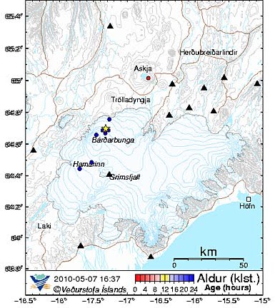
Looking at the earthquake pattern that has been taking place in Iceland, there are a couple of areas of concern:

General view of recent earthquakes in Iceland

The first is the increase in the earthquake activity at Eyafjyallajokull and the spread to Myrdalsjokull (under which sits Katla).

The second is the increasing activity up around Loki.


Note that the stars are for earthquakes above a level 3. Interesting that this is at a depth of around 1.1 km, while the last over 3 one there was at a depth of 3.3 km.

There is still not much activity in the area of Laki – which may or may not be a good sign. But since we are dealing with geological events here, with the difference in scale that they have, even an instant response can be measured in months and years, rather than hours.


Read more!