Showing posts with label LMRP. Show all posts

Wednesday, June 23, 2010

Deepwater Oil Spill - Problems with the LMRP cap

BP issued a press release this morning that read:
NEW ORLEANS -- This morning at approximately 8:45 a.m. CDT, a discharge of liquids was observed from a diverter valve on the drill ship Discoverer Enterprise,which is on station at the MC252 well-site. As a precautionary measure,the lower marine riser package (LMRP) containment cap system, attached to the Discover Enterprise, has been moved off the Deepwater Horizon's failed blow-out preventer to ensure the safety of operations and allow the unexpected release of liquids to be analyzed.

Capture of oil and gas through the LMRP cap is therefore temporarily suspended until such time that the cap can be re-installed. Capture of oil and gas through the BOP's choke line to the Q4000 vessel on the surface continues.

LMRP cap floating free 4 pm June 23, 2010 (Enterprise ROV2)

UPDATE: The cap was replaced at around 6:30 pm and appears now to be working as before the event. The standings in the Solar Car race have been added to the end of the post.

Unfortunately the severe weather in the area today is not helping the effort either.
.
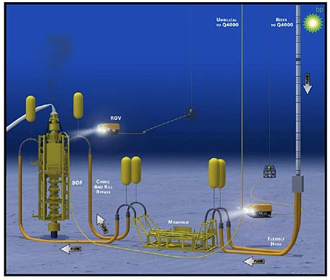
Due to severe weather conditions expected across southeast Louisiana today, June 23, regularly scheduled cleanup and response efforts may be impacted/halted as weather systems move through the area. These efforts include controlled burns, dispersant flights, and booming operations. Source efforts and some skimming vessels may be operating as long as conditions do not exceed their operating limits. Protective boom is in place along many miles of Louisiana’s coastline. Crews will resume cleanups as soon as safely possible. Safety of all personnel is important to the success of this operation.
At a press briefing in Washington on the event Admiral Allen blamed the event on an ROV hitting one of the valves on the vent at the top of the cap and causing it to close. With the vent closed the pressure under the cap would increase (since the flow would have a smaller area to escape through). That increase in pressure was enough to reverse the flow through one of the lines that send warm water down to the cap to keep it warm enough that hydrates don’t form.

It appears, from Joel Achenbach's Washington Post report that oil and gas was found coming out of a line that was pumping the water down, which raises a little question over the flow circuit being used that would allow that to happen? That discovery led to the cap being removed from the well for inspection. Any gas outlet at the surface would pose increased risk to those running the operation and had to be dealt with immediately.

The current plan is to replace the cap later this afternoon, presuming that the blockage has been removed. Unfortunately, without the pressure gage recordings from inside the cap it is not possible to know if the pressure build-up was gradual, which could be explained by this deposition of material in the flow path, or if it was a step-function which would more likely result if an ROV had nudged a valve closed.

As I mentioned earlier the alternate hypothesis is that there has been some crystal growth within the flow path through the cap, which caused crystals to grow, constricting the channel and thus raising the pressure in the cap itself. The pressure jump cannot have been too rapid if the indication of the problem came from the backup of oil and gas out of a water line. And crystals can form either quickly, in large size, or more slowly and insidiously.

Barium Sulfate Crystals growing in a 3-inch I.D. pipe that carried oil from the deposits under the North Sea. (Scale is in cm) (Growths of this size can occur in less than 24 hours).

That having been said, and recognizing that Occam’s Razor may well cut my hypothetical throat one of these days, the transcript of the press conference is now available. The Admiral clearly blames the ROV for the incident
Out of abundance of caution the Discover Enterprise removed the containment cap with the riser pipe and moved away until they could assess the condition.

They have indicated that the problem was a Remotely Operated Vehicle that had been around the (inaudible) package that bumped into one of those vents that allows the excess oil to come out. They actually closed it thereby creating pressure and the backflow potentially off the water vent.

They are checking the containment cap right now that there are no hydrates in the containment cap. They will attempt to reinstall the containment cap and begin producing later on today. If there are hydrates they will probably have to rerun the pipeline, and that will take a considerable amount longer.
At present it appears that they are lowering the cap back into position. The specific event was described as follows:
My understanding was they noticed there was some kind of a burp in the line where there was either natural gas or some reason. They thought they had product—or hydrocarbons coming up through the water line that's usually meant to carry hot water down, which is to heat the pipe, as you know to do away with the hydrate problem.

When they thought that that line might have been compromised, or they have the chance that they might have hydrocarbons coming up through that vent into the Discover Enterprise, which is flaring right now, over an abundance of caution they elected to remove the cap and move the riser pipe and the cap away.

When they moved it away then it's open to seawater. And they said if there is any product there you have the chance for hydrates to form. So before they decide to move it back in they have to check and see if there are any hydrates there. If there are hydrates they are probably going to have to pull the drill pipe and reinsert it once the hydrates are cleared.

And again, the initial indications were that one of the vents, which is allowing the oil to vent so the cap will stay on will somehow might have been dislodged by coming in contact with our ROV. But I think they are trying to validate that right now. They do know that one of the vents was shut when they set the second ROV down to take a look. That's all we have right now. We're continuing to look into it.

But then there was also this
they found this out after the fact when they set their ROV down after they had removed the containment cap that it appeared that one of the vents had been closed. Now the assumption is that was a result of an ROV bumping into it and actually closing the vent. We don't know that for sure. I think we're still developing the facts associated with it. I don't think it's any problem in putting on an exact timeline when we get all that stuff together.

The Admiral also updated the schedule for drawing oil from the BOP through the kill line. The riser to carry that has been installed, and they are now hoping to have that hooked up to a second vessel by next Tuesday. This will increase the production capacity from the well to 53,000 bd.

Given the concern that has been expressed about hazardous vapors being given off over the clean-up site, the Admiral also brought an OSHA representative to the meeting, and he noted:
We have been taking samples again, of worker chemical exposures. Again, on the beaches, in the swamps, on the boats, everywhere that workers are. And I will just let you know, we can discuss this a little more, that we have found no exposure levels to any chemicals that are of any concern.

The main problem we've been seeing down there, the main concern that we've had for worker health and safety has to do with heat. As you know, people are working in very high heat conditions. Very often they are also working with Tyvek suits with chemical protective suits, gloves, which exacerbates the heat problem.

Finally there was this interesting teaser about the possibility of running the production from the well to an existing platform.
I believe BP is in discussion with other industry producers that have rigs in the area that might be useful for that. I don't think they concluded those yet. I just mentioned it yesterday because I was asked about whether or not there were any redundancies or any recourse if we had a hurricane or heavy weather that allowed us to move—or required us to move all of the vessels from the scene.

This would be one way if you are actually connected to another drill site, you would not have to rely on service vessels.
There is more on what would be involved at Upstreamonline (who asked the question).

The update on the solar car race, with the teams resting in Rolla overnight, and leaving at 9 am in the morning:

1) Michigan . . . . .15:48 (hours and minutes)
2) Minnesota . . .17:06
3) Bochum . . . . . 17:28
4) Calgary . . . . . .19:08
5) Stanford . . . . . 19:23
6) Missouri S&T 19:47
7) Kaohslung . . . 22:01
8) New Paltz . . . 25:27
9) Northwestern 27:43
10) Kentucky 28:05

And as I drove home from work car #5 the entry from Illinois State, rolled past me and on to the finish line.


Read more!

Sunday, June 6, 2010

Deepwater Oil Spill - closing the relief ports

The rate of oil recovery from the Deepwater well in the Gulf of Mexico has increased from the 6,000 bd recovered on Friday, to some 10,000 bd which was recovered on Saturday.
On June 5, a total of 10,500 barrels of oil was collected and 22 million standard cubic feet of natural gas was flared.
Looking at the relative flow patterns still leaking from around the containment cap, it is hard to detect much difference in the amount not being captured. This is the current flow (note the white spot in the cloud which is the triangular shape at the bottom of the cap).

Flow at 10 am Sunday

And this was the picture that I posted from the same ROV at the time that the cap was installed

From Skandi ROV 2 10:55 pm 4th June

The triangular elements at the bottom of the cap are more evident. Now the ROV may have moved, but the depth of the cloud beyond the cap is roughly the same, suggesting the same pressure driving it, and if the gap is the same size, then the volume leaving through the base of the cap may well be the same.

The 4,000 bd increase in flow has thus, likely come from the closing of one or more of the relief ports that allowed oil to escape from the top of the cap.

BP illustration of the cap, showing the relief ports with valves

This cap is likely to stay in place for a couple of weeks, until BP can fabricate and install the next step, which will be to reverse the flow of fluid through the choke and kill lines, so that some of the flow can be directed up to the Q4000. This will both help with managing the flow, and also give an alternate path for oil to be recovered, when this first cap is removed.

Read more!

Friday, June 4, 2010

Deepwater Oil Spill - sealing the cap and jet pumps

There has not been much change down on the sea bed where last evening BP were able to put a cap onto the short riser section coming out of the Lower Riser Assembly (LRA) that sits on the Blowout Preventer (BOP) at the top of the well. I have looked in a variety of places for information on steps forward, and did discover that there is a second assembly above the cap, that I had seen, but had not been able to recognize until watching the video on capping available at the Deepwater Response site. It is here that the methanol is sent down to the cap to make sure that no crystals form within the cap. So for those who wish to keep the right names for the right parts, take note.

The cap, drill pipe, LMRP and riser assembly used to cap the well.

And given that I was calling the cap the 7th generation LMRP when it was (as the big 4 on the side of the yellow structure showed) neither, means I need to take my own message to heart. In this post I am going to talk about the seal under the cap.

There are four ports on the top of the cap, that continue to allow the oil that is flowing into the cap to flow back out while the cap was initially positioned, and to reduce the flow up the BP, until the system has been checked out to ensure there are no unforeseen problems. BP only slowly raised the flow rate up the pipe when they first started using the Riser Insertion Tool (RIT) starting out with a flow of around 1,000 barrels/day and then ramping it up, at the time reporting that flow ramped up first to 2,000 bd and then up to 4,000 bd. However they later rescinded the latter number and dropped the maximum flow level to around 2,200 barrels a day. Oil and gas have started flowing up to the drillship at the top of the riser where the oil is separated and stored, and the gas is being flared. (This was taken during the flare from the RIT operation).


However the flow out of the RIT was monitored, and higher rates have now been reported.
On May 25, 2010, at approximately 17:30 CDT, the RITT logged oil collection at a rate of 8,000 barrels of oil per day, as measured by a meter whose calibration was verified by a third-party. Based on observations of the riser, the team estimated that at least 10% of the flow was not being captured by the riser at the time oil collection was logged, increasing the estimate of total flow to 8,800 barrels of oil per day. Factoring in the flow from the kink in the riser, the RITTI Team calculated that the lower bound estimate of the total oil flow is at least 11,000 barrels of oil per day, depending on whether the flow through the kink is primarily gas or oil.
With the full flow now being emitted through the single confluence of the riser and BP flows at the top of the remaining riser section on the BOP, a full estimate of the leak will, no doubt, not be long in being announced.

The high volume of flow means that there need to be cautious progress in capturing all the oil and gas and sending it up the DP. However there is still a little communications conflict, since there were some reports that the taps bypassing the oil/gas would be closed later today, however at 10:43 pm the Enterprise ROV 2 was still showing an open port.


Oil was also leaking out of the bottom of the cap, which is, even when almost all the oil is being recovered, likely to be a good thing in small quantities, somewhat less than this.

From Skandi ROV 2 10:55 pm 4th June (The Skandi Rov 1 has the picture from the other side, also of the bottom of the cap).

Why is this? Well the way in which the Shear was used to cut the end of the riser and BP means that it is likely to be impossible at the present time to get a good strong seal around the chamber between the flow into the cap from the BOP and that out into the BP up to the LMRP.

When a stream enters a chamber through one port, and exits through another, both of relatively small size, then the jet will create a vacuum in the chamber, which pulls fluid from the surroundings into the chamber and carries it, with the jet fluid into the second port. I am going to embed a short video of a commercial down-hole video and am not endorsing anything but the animation shows you how the jet pump works. (And the flow in the Gulf is easier than that shown here ).

Animation of an oil well jet pump. There is a competing design here (shorter video too)

The reason that it is critical in this operation is that the fluid outside the cap is seawater. If the jet pumping action were to become too efficient as all the oil flowed from one passage to the other, then the “jet pump effect” would draw cold seawater into the chamber and the problem of hydrate generation and blocking of the flow path would be back to block the cap, as it did top hat. By not getting all the flow into the second pipe it should be possible to drop the suction in the chamber to the point that a little oil still leaks out (treated with dispersants) but the majority goes up the well. Getting this right should prove an interesting exercise. (But isn’t calculating this what the “best and the brightest” – Dr. Chu’s team - are there to do?)

Flow control is achieved, simplistically, with a valve at the top of the riser on the Enterprise. By adjusting the flow the valve effectively controls the pressure at the top of the riser and thus also at the bottom.

Incidentally in other circumstances jet pumps are neat tools. One of my students developed a high pressure one for use in lifting high-level radioactive waste out of nuclear waste storage tanks (you want to minimize water use, and do this by upping the driving jet pressure). Worked like a charm, when used in the real tanks. They are also used as remote inexpensive pumps in mines, lying in depressions where water can collect. The water collects, a float valve lifts and the jet flows, sucking the water away. As the water disappears, the float drops and the jet switches off.

Oh, and for those who have ideas on how to deal with any part of this problem, the Government is stepping up the ways in which you can get funding. The process goes through the Federal Business Opportunities Webpage where there is a Broad Agency Announcement on the subject. It would be more fruitful to contact them.

Read more!

Thursday, June 3, 2010

Deepwater Oil Spill - capping the riser - Part 1

The vertical section of the riser was cut, using a Shear at 9 am this morning.

Lower Riser Assembly (LRA) atop the Blowout Preventer (BOP) at the Deepwater Horizon well, with the bent riser removed, waiting for the arrival of the Lower Marine Riser package (LMRP) The oil and gas are rising vertically, from the top of the riser, the drill pipe (DP) and the saw cut in the side of the riser (just down from the top of the shear).

At 8:30 pm the ROVs maneuvered the latest version of the “top hat”, variation 7, of the LMRP over the top of the LRA. As the new cap was lowered into place it was surrounded by clouds of oil and gas, making the actual progress of the event somewhat difficult to follow. The new variation had been finished yesterday, to accommodate the changing upper surface of the remnants of the well.

Building LMRP 7 on June 2nd at Port Fourchon (BP )

The Lower Marine Riser Package (LMRP) was first connected to the riser, an to a methanol feed that would help, between them, to inhibit the formation of methane hydrides when the gas came into contact with the surrounding cold seawater. It was then slowly lowered to the site. (You can see the seal, referred to later, along the bottom edge - h/t KLR).

Interior of the LMRP as it was lowered. (KLR)

Once it reached the right depth it was moved across into the fountain of oil and gas, and down over the top of the riser.

Lowering the LMRP into the cloud of oil from the riser.

The initial attempt halted after a while, and by 9 pm the situation was, for while static. The cap was sitting apparently on the rubber seal that had been designed to fit between the LMRP and the flange, but the amount of oil that was leaking out of the bottom of the LMRP, was still a considerable amount, even though some of the flow was also being bypassed through ports on the LMRP that could later be closed.

Flow through a relief port on side off the LMRP to relieve the pressure within it.

Leakage around the seal between LMRP 7 (yellow), the seal (greenish black) and the LRA. (white)

The question now arises as to whether the LMRP could be lowered sufficiently that it could seal to the flange surface, since it was no longer possible to get the seal needed on the upper surface of the riser, given that it had been distorted by the Shear which had cut the bent riser away.

There was a pause, while the engineers had a bit think for over an hour. Looking at the cloud of oil coming out, it does contain small white specs that could be either methane hydrates or drops of the dispersant. And now, at 10:30 pm, there is a little more action.

Oil and gas coming out from under the LMRP

Leaks under the LMRP at 10:30 pm

For those who may not remember, this was the initial plan as it was proposed.

The Lower Marine Riser Package (LMRP) option

So far it is not quite as simple as the sketch would suggest. But I will put this up, and then update, as changes appear. But we may be in for a bit of a wait as they may only slowly close the valves and direct the flow to the surface, as they did with the first oil capture at the RIT. They will be checking slowly through the process to see that as little as possible goes wrong, as they ramp up the flow, and slowly turn off the bypass valves.

Read more!

Monday, May 31, 2010

Deepwater Oil Spill - cutting metal underwater

The decision to cut the riser and drill pipe (DP) from the top of the Blow-Out Preventer (BOP) as a first step in putting the Lower Marine Riser Package (LMRP) over the leaking oil well in the Gulf of Mexico is not quite as easy as it might sound to a layman. This post is going to talk a little about a couple of the problems, as well as an alternate way of doing it, and should end with a possibly slightly amusing anecdote.

The current plan is to carry out the operation in two parts, first the main body of the riser and contained BP will be cut using a large shearing machine, and then a precision cut will be made with a diamond wire cutter to prepare the surface to act as a support and seal for the LMRP. (Illustrations are below the fold). There are a couple of reasons why this is going to be done this way, and one or two concerns that will need to be watched as the operation continues.

Part of the problem lies in the considerable stress that the metal is under, which may make it more difficult to get the precise cut that is needed for the sealing surface. The weight of the collapsed riser on the kinked section of the riser means that the metal is under a considerable stress, and as the cut is being made that stress is going to be released. This is a particular problem if the saw blade is in the cut as that stress releases. As an illustration large diamond wheels are used in granite quarrying as a way of making the first cut in a new layer of rock. As the quarry works down into the deposit, however, the stress in the rock increases. So that when the diamond saw cuts into the layer, the walls will move in slightly. Now if the diamond saw is rotating until it is removed, it will grind away that small movement and there is no problem. But if the saw is removed, and the cut restarted the next day, then it might be necessary to recut the same depth again, because the walls have moved in that far. The much worse thing to do is to leave the diamond saw in the cut overnight – the walls will move in and pinch the blade and you can’t get it back out without destroying it. Did I mention these blades can cost up to $100,000.

So given that it would be a bad idea to break the diamond wire in the cut, or trap it for that matter, the first step in the process is to take some of the load from the riser by cutting off the majority of the fallen pipe. To make this simpler and since the quality of the cut is not important, this will be done with a large shearing machine.

Large shearing machine used to cut through the main section of the riser (Unified Command )

For the second stage in the process the riser and pipe will be cut, at the top of the BOP using a wire saw to cut through both pipes. The diamond wire, which is held under tension in the design, should give a relatively smooth surface that can be used for the sealing surface to the LMRP.

One of the problems in using this tool, which is rather sensitive (in other circumstances we have broken several wires in a smaller model) is dealing with the central DP as the cut is being made, and with the flow of oil and gas past the wire, which can send it into vibration, over the relatively long cut.

Wire sawing the riser and drill pipe (Unified Command )

The two pulleys at the top of the saw are used, as well as guides, as tools to keep the wire under the correct level of tension.

A version of an underwater wire saw (Wachs)

It is relatively slow to cut, (perhaps 10 to 30 sq ft/ hour, depending on power and blade size) and requires patience to keep the applied loads at the right level (the joy of automatic equipment over manual operation). There are still possible risks, due to the remaining load on the metal being cut as it is being made, since the amount of metal left gets less over time. As a result it is likely that, in the same way as a forester will use wedges to stop the cut closing as he chops down a tree, so small metal wedges will be put into the cut in this case. The only difficulty that this imposes is that it will be difficult to access the central BP and difficult to deal with that, once cut through, since it is within the riser and not accessible. Hopefully it will be held in place by the bend of the pipe and riser, until the wire has passed through it.

Over the past twenty years diamond wire sawing has become more common as a way of cutting through a variety of materials. It has the advantage of making a relatively narrow cut , and the ability to cut through objects made of different materials, such as reinforced concrete. The cutting wire used to have small diamond particles embedded in the steel of the wire, but in more modern varieties the diamonds are embedded in a plastic such as Teflon, and set as beads along the wire, allowing better cooling during the cutting process.

Segmented diamond wire – new so that the paint is still over the diamonds (Wachs)

Now my students will tell you that I have a bad habit of slipping commercials for another technology into lectures, and so I am going to indulge, and mention that there is an alternate technique that could be used instead. And that is the use of a high pressure abrasive laden, waterjet cutting stream. These are becoming increasingly used in industrial manufacturing, although in that use the technique usually involves a different way of adding the abrasive to that which would be used in the current problem. In the conventional way of adding abrasive it is mixed into the jet after the water is accelerated, and, in the right circumstances, we have been able to cut through half-inch titanium with an accuracy of 0.001 inches. Those jet systems operate at pressures from 40,000 psi to about 90,000 psi. In the current case the abrasive is added to the water from a pressure vessel, and the technique is known as abrasive slurry jetting (ASJ). It allows equivalent cutting at about a tenth of the jet pressure (i.e. 5 - 10,000 psi). The tool has been developed for cutting off different oilwell parts from the wells under the North Sea. Because the jet cuts away from the nozzle, it can cut, for example, out from the center of a set of drill pipes, one nested inside the other, and separate them, as one of the last stages in decommissioning a well. It has a problem with range, the jet cutting to a shorter distance as the back pressure in the water increases, and for cutting down to 500 ft (the deepest we have tried) it can be improved to cut large risers by adding an air sheath around the outside of the jet.

One alternate way that is used for cutting tanks and other containers with possibly explosive content is to use a chain crawler around the pipe. This way the jet does not have to cut quite as far through the water.

Cutting a pipe using a crawler (NLB )

(And for those who question whether jets would work under this depth, Gulf Oil – as was – used an abrasive waterjet to drill a well down to 15,000 ft back in the early 1970’s but a fire destroyed the equipment and the research was stopped).

To end with the anecdote – which relates to the cleaning of oil rigs for inspection. The problem that arises is that barnacles and a variety of sea creatures and plants grow on these structures, and need to be removed. The historic method of doing this was to give a diver a chipping hammer, and send him down to chip off the offending coating. Now when a diver is in the sea there is not a lot of resistance, and so one has to clamp onto something to develop enough thrust to effectively use the hammer. The only object available is the rig itself, and wrapping one’s legs around a strut works to give the platform. The only problem is that the strut is covered in barnacles – ouch!

So the waterjet industry developed a zero-thrust gun (in other words the cutting jet on one end is matched by a jet of similar power on the other, so the forces are balanced) and the diver does not need to hold onto anything. It was taken out to one of the rigs in the North Sea and given to one of the divers.

He took it, without a word, and disappeared over the side of the rig. He was down underwater using it for about fifteen minutes and came back to the surface. He didn’t say anything, but walked over to the chipping hammer. He put down the lance, picked up the chipping hammer, and walked to the side of the platform. “So long , you son of a . . . .”, he said, and threw it overboard.

It was one of the fastest adaptations of a change in technology around the world that I have seen. Anyway I will talk about using jets for efficient cleaning in another post. Enjoy the day!

Read more!

Sunday, May 30, 2010

Deepwater Oil Spill - why Top Kill may have failed

The Top Kill attempts have failed, and the Government has a response.
He (President Obama) said US Energy Secretary Steven Chu was leading a team of "the world's top scientists, engineers and experts" in devising a contingency plan should the "top kill" attempt fail.
But while waiting for that, and for the Lower Marine Riser Package (LMRP) I thought I would spend a few paragraphs discussing why Top Kill may have failed.

In a couple of earlier posts I wrote about how it was necessary to fill the gaps that ran through the Blow-Out Preventer (BOP) either with spheres and triangles or with wire(string would act similarly). To refresh your memory, in the initial simpler analysis I had put up a simple sketch of the BOP and well, to show how the blocking particles were injected.

Simple approximation of the situation

Now unfortunately that diagram missed a significant part out, and that is that there are three sets of pipes leading down into the well. These are the well outer casing, which, surrounded by a layer of cement, holds the BOP in place. Then there is the production casing, which had just been set to the full depth of the well. And there is the drill pipe that, at the time of the incident, extended down 8,367 ft from the platform, or roughly 3,367 ft below the BOP. That drill pipe (DP) had previously been used to locate the production casing at the bottom of the well, and itself now rode inside that production casing. In most normal operations it is closed at the bottom by a drill bit, but (and I’ll come back to this later) it had just finished the cementing of the production casing into position, and once it detached from that and was being pulled from the well, it was an open pipe all the way up to the rig floor. And in that condition it could be used for other things. By pulling mud out of the DP and transferring it to the mud pits (or standoff vessel), the level in the riser would fall and be replaced by seawater flowing in at the top. Unfortunately this also lowered the weight of mud in the well, and that is what caused the oil and gas to flow into the well.


Outside of the DP is the casing and cement segments that make up the outer lining of the well. The diagram presented in Congressional testimony, shows these various pipes, except for the central drill pipe.

Casing and cement down the Deepwater well

BP do not know, but believe that the oil is getting into the well through the cement wall at the bottom of the well, and probably rising up the well through the empty space (annulus) between the production casing and the outer lining of the well. However the oil and gas may have broken through the bottom of the cement plug and be rising up within the production casing, in which it is also rising through the BP once the oil reaches its lower end.

Most normal blowouts occur when the well is being drilled, and mud is flowing down, through the drill bit, and then back up the space (the annulus) between the DP and the rock wall. Thus, when there is a blowout, the oil and gas that flow into the well normally flow up this outer passage to the rig, and give the spectacular fountain of oil. The BOP was invented (by Harry Cameron and Jim Abercrombie) to stop that flow and to protect the crew at the surface. Because the flow is normally up the outside of the drill pipe, the initial BOP designs were rams that pushed seals across the flow path through the BOP, and sealed against the side of the DP.

BOP open allowing flow through the annulus (ASME )

BOP closed against the pipe, sealing the annulus (ASME )

A BOP could have two of these mounted so that one sealed to the production casing in the well, and one to the drill pipe, but if underwater then the production casing is tied back to the Wellhead Collet Connector, and then the only tube running through the BOP will be the DP, to which they will seal.

BOP connection to casing at the seabed (PCCI report for MMS)

The problem that this leaves, in the current situation is that the pipe that runs through these two seals is open at the bottom to the oil flow. So how can the flow through this be stopped?

The answer is to mount a top ram set that has a set of shear cutting blades on it, that will cut through the pipe and seal the full face of the well.

Shear blades to cut through the DP and seal the well (Varco )

The BP should shear, but would be held in place by the grip of the annular sealing rams below.

In this case it seems to be recognized that for some reason this shear event did not totally succeed. Thus the pipe was not totally severed and the two shear plates did not fully move over one another to complete the seal.

Now this is where the problem arises, because, in part, that pipe is still open at its lower end. If the leak is around the outside of the pipe, through a gap that has generated between the pipe and the annular seals, then the use of the junk shot to fill the cracks and gaps could conventionally have worked. But the configuration of the rams on the Deepwater Horizon had changed from the initial simpler configuration to add seals for occasions where the drill pipe was not in place.

Ram layout on the BOP (Times Picayune)

And the "junk" is being injected at the bottom of this stack.

Section through the BOP, showing the anticipated mud flow path (initially from BP)

If the leak is coming up through the remnants of the drill pipe then life is complicated. It can’t all be coming up through an undamaged pipe alone, since it was the far open end of that which was successfully closed at the beginning of the remedial steps, but if it is coming through the pipe and leaking out at the shear rams into the annulus that feeds into the riser, and out to the sea, then putting sealing particles into the bottom of the BOP to seal the cracks, could have sealed some of the leakage around the DP trapped in the shears, but not that flowing through the shears in the remaining pipe section.

The reason that it can’t is that the access to that flow is occurring 3,367 ft below the riser, and there is no easy way to get the sealing particles down that far. If they are mixed with mud and pushed down the well to that level and then released they have a different problem. The hope when they were released into the well was that the flow of the current would be enough to carry them up to the cracks that they could seal. But if they have to be carried down to the zone where the oil remains, then their density may be sufficient, if they get into the flow without enough speed to lift them up into the BOP to cause them to sink to the bottom of the well.

The materials that BP tried included materials that might float on the surface, and might not
Those materials, including fibrous pieces of rope and chunks of rubber, were supposed to force more of the mud down the wellbore, but ultimately it did not work.
Rubber has a specific gravity of 0.91 and rope varies from 0.9 to 1.4. But remember that at that depth any buoyancy from air entrainment would be lost.

In other circumstances it might have worked, If they could have dropped the DP out of the shears perhaps, but they couldn’t and it didn’t. So on to the LMRP.

UPDATE: Thinking about this a little more, I had two more thoughts. The first is that once the LMRP preparation cuts off the riser and the bent drill pipe that the full weight of the pipe below the shears may come onto the section in the shear jaws at the moment, pulling them further out of alignment and increasing the flows. It could also cause the pipe to drop out of the jaws, pulled out by the underlying weight, and hopefully not distorting them too much so that in the best of worlds they could then be cranked shut.

One could also, once the bent riser and pipe had been cut, go in down the pipe bit that extends up, go down past the annular seals with an abrasive jet lance (most of the flow is around the DP as we have established above) and cut it off, right above the shears. Then partially open the shears, drop the pipe out, and close them again. If they move all the way closed, without the obstruction, then the well may be sealed.

(Note because a) this is really a sort of Tech Talk, and b) its a nice day, there won't be the regular Sunday tech talk which would have been on coal mining today - it is postponed, as was the Saturday discussion of state climate changes - hopefully I'll be able to get back to both of those before long).

Read more!

Saturday, May 29, 2010

Deepwater Oil Spill - the end of Top Kill

BP and Admiral Landry just held a Press Conference in which they said that, based on a decision 90 minutes ago, by the “best and brightest minds” that it was time to move on the next option, the Lower Marine Riser Package (LMRP). BP was unable to block sufficient flow out of the well to make the injection of cement possible, and thus to kill the well. They had made, I believe he said three attempts to inject material (the junk shots) without being able to get that material to block the passages through the Blow-Out Preventer (BOP) . (Unfortunately I missed a large part of his opening remarks, and thus have only the question response to go on at present). The volume of mud used did not appear to have changed from earlier reports at some 30,000 barrels.

Mr Suttles said that they had given the technique every chance, but could not get it to start to provide an effective seal. They had, however, determined that the majority of the pressure restrictions to the flow of oil was coming from some resistance within the well itself, and from the BOP. Since the riser above the BOP was not contributing much to the resistance, and thus to control of the oil flow, the next plan is to remove it, using a band saw device (of which pictures will be available) and then to lower the LMRP onto the existing BOP. They intend cutting the surface that the LMRP will sit on flat, so that it will give a good, but not perfect seal. Thus there will be some leakage around the joint, and they will monitor that and use dispersant as appropriate.


The new change should take somewhere between 4 and 7 days to implement. The assembly, which has been constructed, and is not the Top Hat assembly built earlier, to fit on the bottom of a riser. Flow of oil from the LMRP will rise up a 6 7/8 inch drill pipe within the riser (the same size as the one currently fitted to the RIT). The riser will also carry hot water down to the LMRP to protect against the formation of hydrates.

He noted that their inability to stop the well “scares everybody” but is reasonably confident (no success percentage estimates) that this will collect the majority of the oil and gas. Because they do not know the flow path of the oil below the seabed it is difficult to estimate what is actually going on in terms of oil path below the BOP. Thus they are, again, trying something that has never been done before, but expect, based on the RIT, that it will work.

On being asked about the cleanup of the dispersed oil – he pointed out that the reason that the dispersant was used was to break the oil into small droplets. These are small enough to be consumed by the microbes in the sea, and thus there is no plan to do other than let nature take its course. For the oil on the surface, they are getting better at spotting oil pools and sending skimmers to deal with them.

The Admiral drew attention to the article on Hurricanes and the Oil Spill which is available at the Unified Command We site.

The relief well is about half-way through the rock it must drill (about 6,000 ft below sea level) but progress will slow as the well deepens.

The Lower Marine Riser Package (LMRP) option

Read more!

Monday, May 24, 2010

The Gulf Deepwater Oil Spill - the Top Kill attempt

The next attempt to shut off the flow from the leaking BP well in the Gulf is still aimed to occur early Wednesday. The attempt will use the “top kill” method to try and kill the well. WhileI have described this in earlier posts, the Unified Command have put out a video animation of the process, and there was an earlier diagram. So I am going to use these, which are simplified explanations, with some additional comments and tie it in to more facts that came out of briefings today, to try and give a more detailed explanation. Here is the animation:


Before the process could begin, however, it was necessary to significantly modify the blow-out preventer (BOP) that sits on the top of the well. For those interested (its a bit like watching one of the operations on the space station) BP has assembled a short (5 minute) selection of the video footage of the various steps. When watching it, you should bear in mind that the ROV’s carrying out the different steps have to operate in a relatively crowded environment.

The well neighborhood


The tasks to be done included removing, modifying and replacing the control box (or pod) that operates the valves that open and close the flow lines into the choke and kill lines on the well. Other than this, the flow lines to the flow and choke lines themselves had to be replaced with the feed lines (shown in the animation) that will carry the mud into the well. Even tightening a fitting that had worked loose takes time, when it has to be done using an ROV (with the operator at the surface needing to see what he is doing while getting the ROV to hold the necessary wrench and turn the fitting). The old feed lines then had to be cut from the BOP, and replaced.

ROV image showing the control pod fitting being tightened

This involved
* cutting off the choke and kill line connectors
* Cutting the bolts on a flange
* Removing the clamp
* Removing the pipe flange end
* Buffing and cleaning the pipe end
* Preparing to attach the new jumper lines. (This had to be done for each feed line)
* A special hydraulic connector attached to the 150-ft jumper cables was used to latch onto the old inlets. This is slow work (as the video shows) and as a result this part of the work has taken seven days. (The jumper shown in the video was attached on the 16th and chained down into position on the 17th.)


When the connections and fittings have all been made and checked, and the control pod operation validated, and the necessary permits from MMS and others obtained, then the process can begin.

The process will be controlled from the Q4000, which is designed to have the capabilities needed. Two lines feed from the vessel to the BOP. The first carries the control feeds through an umbilical, while the second is a riser that carries the mud down to the flexible hoses and jumper lines into the BOP itself. This mud, at about twice the density of water, will be delivered from the two high-pressure Schlumberger MD 1000 mud pumps made by Schlumberger and will flow through the two feed lines that were the choke and kill circuits, into the well itself, below the main rams of the BOP.

Top Kill Circuit

The pumps will deliver the mud into the lines at a pressure of 6,800 psi, but as Kinuachdrach has correctly noted, it will then acquire the pressure from the full 5,000 ft column of mud as it flows down to the BOP, and enters the flow channel carrying the oil. Now we know that the BOP rams at least partially closed. If they are planning on using golf balls for the “junk shot”, it is feasible to surmise that the maximum width of the flow channel is no more than a third of a golf ball diameter. Not arguing the merits of American vs British ball sizes, let us assume that this is roughly half-an-inch (though it may have a greater length).

However, as flow volumes go up it requires more and more pressure for the fluid to get through a small gap. And at a given delivery pressure, only a certain flow volume will thus be able to escape that way. As long as this pressure exceeds that in the well, the net result will then be that the mud begins to push the oil and gas back down the well, and the well fills up with mud. The weight of that mud should then be enough to exert a pressure on the bottom of the well that is enough to exceed the fluid pressure in the rock and therefore stabilize the well and stop the flow of fluid out. Cement can then be pumped into the well to seal the top end. (Or with the flow stopped another BOP can be put on the well to seal it). The main worry is that the hole in the top of the BOP is small enough to contain the additional flow volumes, and not allow the entire flow to escape upwards rather than being forced down the well. The higher flows might, in addition, if they do exit the riser, further erode the openings. This could increase the oil flow, as it lowers the resistance. (If this happened then the LMRP will be deployed).

There are, however , a number of caveats to this operation. If the pressure in the well gets too high it can cause fractures in the rock at the bottom of the well, and this can cause the mud in the well to flow into the rock, rather than sitting in the well holding the pressure against the oil pressure.

There are also concerns with the condition of the bottom of the well, and whether this will have any impact on the flow of mud back down to the well and in sealing it.
Suttles said BP could not be certain but diagnostic tests on the well seem to indicate the flow is not coming up the main bore.

The well also contains obstructions that are restricting the flow rate.

It is impossible to know for certain what those obstructions are, Suttles said, but cured cement and rocks from the formations that crews drilled through could be partially clogging the well.

If the top kill fails, then the next step will be to cut off the riser, and use the top hat that is sitting on the sea bed near the well, to capture the flow in the LMRP option.

The Lower Marine Riser Package (LMRP) option

Were it me, I might contact Atlas Tocco and have them look into connecting up an induction heating coil around the outside of the bottom of the riser section. Might give them the occasional additional bit of heat on the inside surface that might be needed to dislodge any inconvenient crystals that might form., without interfering with the internal flow channels.

As a point of scale for the video from the riser leak, the amount of dispersant that is being ejected into the water is about 14,000 gallons a day or about 10 gallons a minute (quarter of a barrel roughly). A 5,000 bd flow is around 150 gals/minute.

This came from Doug Suttles teleconference in which he noted that BP have now spent around $800 million. He noted that oil levels in the water near the well are being measured at 10 ppm )(parts per million), against an EPA limit for oil discharge which is 15 ppm. However it is early in the monitoring cycle, and with a fleet of government sampling vessels now starting to work, the plumes and oil dispersant paths will be mapped in more detail in the weeks ahead.

Read more!