Showing posts with label horizontal wells. Show all posts
Friday, November 28, 2014
Waterjetting 27d: Drilling at a fixed diameter
In the last post I described how we initially came up with a simple design for drilling through material, using an axially aligned jet and a larger jet offset to one side at an optimal angle of around 20 degrees.
One of the problems with the use of this design is that the outer jet has to remove all the material in front of the nozzle during the time that it rotates around and advances the distance of the incremental feed rate. If it does not then there is a significant problem. Consider the case where the drill penetrates through a layer of limestone, while drilling otherwise in sandstone.
Figure 1. Sectioned waterjet drilled hole through a sandstone:limestone:sandstone sandwich of rock.
Note that although the hole does not deviate as it goes through the harder material since, unlike conventional drills, there is no mechanical contact between the high-angled rock and the nozzle assembly. But the hole reduces in size. If the hole reduces in size below the diameter of the nozzle holder, this will not contact the rock until it has passed behind the plane of the reaming jet. In other words the only way the blocking rock can be removed is to back the nozzle along the hole so that the reaming jet can hit the material blocking progress.
Figure 2. Drill passage blocked by protruding rock in the path of the nozzle body, but behind the cutting plane of the inclined jet.
One way to ensure that this is not a problem is to advance the drill at a slower rate, with the rate of penetration controlled by the ability to cut the hardest rock that the drill will pass through. The problem with that approach, and concurrently that of setting a fixed advance rate, is that, at the same advance rate and rotation speed, the drill will drill through different rocks at a different diameter. While this can be an advantage, in a limited number of cases that I will discuss in a later post, in most cases it is better if the hole is at a relatively constant diameter.
So how can we solve this problem?
One approach taken in Australia was to change the design and location of the cutting jets. Rather than have a single jet cutting out to the perimeter of the hole, two jets were used, but crossed over the axis and cut on the opposite side to their location. This had an additional advantage over the initial design in that, when drilling longer holes (and this went on to drill horizontal holes that ranged up to a kilometer in length IIRC) the head was balanced and so did not wobble and get out of alignment because of the force imbalance.
To overcome the problem of drilling at too small a diameter additional reaming jets were placed on the front of the nozzle assembly, so that he hole would be reamed to the diameter needed to allow the support hose access.
Figure 3. The addition of a pair of reaming jets. Note that offsetting the two front nozzles will also allow them to put a torque on the front part of the nozzle, which can therefore be self-rotating from the left hand of arrow A forward.
But the problem is not completely solved with these changes, since should any rock protrude into the hole in the distance A, so that it hits the larger diameter that follows, again it is not possible for the reaming jets to cut this rock without backing up the drill.
There is another problem, in drilling horizontal holes where the hole diameter can vary. Consider that if the drill goes into a softer material then, at constant advance (ROP), the hole diameter becomes larger. As the drill moves over this larger hole it will be riding on the floor of the hole, and thus the front of the drill will tip forward into the floor of the larger hole. This will incline the drill downwards, and so the hole will no longer be of constant alignment, but rather will gradually, over distance, tip increasingly downwards.
It is therefore critical that the hole be drilled at a relatively constant diameter (allowing for some hole roughness). How to achieve this? The answer is to put a gaging ring or collar of the required hole diameter, in the cutting plane of the rotating jets.
Figure 4. The use of a collar at the front of the nozzle to ensure the hole is cut to the right diameter.
It itself this isn’t sufficient to give the hole a constant diameter, since there is still the problem of drilling through materials of differing resistance. To overcome that problem we put a spring at the back of the drill, with a contact switch to a valve on the feed to the hydraulic motor powering the drill advance. Thus the drill would start to rotate, and the motor would increase the speed of advance until the collar bumped up against the rock. At that time the spring would compress, the contact switch would close, and the advance would momentarily stop. The drill would rotate around and remove the obstructing rock, the spring would expand opening the flow to the motor, and the drill would move forward. It may sound as though it would be a stuttering advance, but when we tried it in a mine you couldn’t tell that the mechanism was working, apart from the hole being of constant diameter, and by watching the spring. It drilled at between 7 and 12 ft a minute in an aggressive sandstone.
Figure 5. The drill assembly used underground. The hydraulic advance motor (it pulls the drill forward using the chain drive) can be seen under the drill sash (the red and grey bar – painted in 1 ft intervals).
In a normal drilling operation when a drill intersects a previously drilled hole at a shallow angle, then the second drill will follow the path of the first hole, and cannot drill through the opposing wall at that shallow angle. (We know this from experience having broken two drill steels trying while excavating the OmniMax Theater under the Arch in St. Louis). But with the waterjet drill we were able to make to second drill cross the intersection.
Figure 6. Photo down one drill hole, showing the point where the hole intersected a second, and crossed without deviation.
Hopefully there is now enough background so that next time I can talk a little more about the effects of borehole pressure on drilling performance.
One of the problems with the use of this design is that the outer jet has to remove all the material in front of the nozzle during the time that it rotates around and advances the distance of the incremental feed rate. If it does not then there is a significant problem. Consider the case where the drill penetrates through a layer of limestone, while drilling otherwise in sandstone.
Figure 1. Sectioned waterjet drilled hole through a sandstone:limestone:sandstone sandwich of rock.
Note that although the hole does not deviate as it goes through the harder material since, unlike conventional drills, there is no mechanical contact between the high-angled rock and the nozzle assembly. But the hole reduces in size. If the hole reduces in size below the diameter of the nozzle holder, this will not contact the rock until it has passed behind the plane of the reaming jet. In other words the only way the blocking rock can be removed is to back the nozzle along the hole so that the reaming jet can hit the material blocking progress.
Figure 2. Drill passage blocked by protruding rock in the path of the nozzle body, but behind the cutting plane of the inclined jet.
One way to ensure that this is not a problem is to advance the drill at a slower rate, with the rate of penetration controlled by the ability to cut the hardest rock that the drill will pass through. The problem with that approach, and concurrently that of setting a fixed advance rate, is that, at the same advance rate and rotation speed, the drill will drill through different rocks at a different diameter. While this can be an advantage, in a limited number of cases that I will discuss in a later post, in most cases it is better if the hole is at a relatively constant diameter.
So how can we solve this problem?
One approach taken in Australia was to change the design and location of the cutting jets. Rather than have a single jet cutting out to the perimeter of the hole, two jets were used, but crossed over the axis and cut on the opposite side to their location. This had an additional advantage over the initial design in that, when drilling longer holes (and this went on to drill horizontal holes that ranged up to a kilometer in length IIRC) the head was balanced and so did not wobble and get out of alignment because of the force imbalance.
To overcome the problem of drilling at too small a diameter additional reaming jets were placed on the front of the nozzle assembly, so that he hole would be reamed to the diameter needed to allow the support hose access.
Figure 3. The addition of a pair of reaming jets. Note that offsetting the two front nozzles will also allow them to put a torque on the front part of the nozzle, which can therefore be self-rotating from the left hand of arrow A forward.
But the problem is not completely solved with these changes, since should any rock protrude into the hole in the distance A, so that it hits the larger diameter that follows, again it is not possible for the reaming jets to cut this rock without backing up the drill.
There is another problem, in drilling horizontal holes where the hole diameter can vary. Consider that if the drill goes into a softer material then, at constant advance (ROP), the hole diameter becomes larger. As the drill moves over this larger hole it will be riding on the floor of the hole, and thus the front of the drill will tip forward into the floor of the larger hole. This will incline the drill downwards, and so the hole will no longer be of constant alignment, but rather will gradually, over distance, tip increasingly downwards.
It is therefore critical that the hole be drilled at a relatively constant diameter (allowing for some hole roughness). How to achieve this? The answer is to put a gaging ring or collar of the required hole diameter, in the cutting plane of the rotating jets.
Figure 4. The use of a collar at the front of the nozzle to ensure the hole is cut to the right diameter.
It itself this isn’t sufficient to give the hole a constant diameter, since there is still the problem of drilling through materials of differing resistance. To overcome that problem we put a spring at the back of the drill, with a contact switch to a valve on the feed to the hydraulic motor powering the drill advance. Thus the drill would start to rotate, and the motor would increase the speed of advance until the collar bumped up against the rock. At that time the spring would compress, the contact switch would close, and the advance would momentarily stop. The drill would rotate around and remove the obstructing rock, the spring would expand opening the flow to the motor, and the drill would move forward. It may sound as though it would be a stuttering advance, but when we tried it in a mine you couldn’t tell that the mechanism was working, apart from the hole being of constant diameter, and by watching the spring. It drilled at between 7 and 12 ft a minute in an aggressive sandstone.
Figure 5. The drill assembly used underground. The hydraulic advance motor (it pulls the drill forward using the chain drive) can be seen under the drill sash (the red and grey bar – painted in 1 ft intervals).
In a normal drilling operation when a drill intersects a previously drilled hole at a shallow angle, then the second drill will follow the path of the first hole, and cannot drill through the opposing wall at that shallow angle. (We know this from experience having broken two drill steels trying while excavating the OmniMax Theater under the Arch in St. Louis). But with the waterjet drill we were able to make to second drill cross the intersection.
Figure 6. Photo down one drill hole, showing the point where the hole intersected a second, and crossed without deviation.
Hopefully there is now enough background so that next time I can talk a little more about the effects of borehole pressure on drilling performance.
Read more!
Friday, May 4, 2012
OGPSS - a little more detail on hydraulic fracturing
There is a real, practical limit to the amount of oil that can be recovered from a reservoir. Depending on the availability and economic viability of different technical approaches that limit might be less than 25% of the total volume of oil originally in place, or it can be more than 50%, as has been achieved in some of the fields in the Kingdom of Saudi Arabia(KSA). But one cannot get out more oil than is originally there, and in most cases it is difficult to reach even half that value. However, where the volumes of oil that have been left by conventional methods remains high, as it does in the KSA, then the use of advanced technology, as I began to explain last time, become easier to justify.
KSA is now reaching the point where the easy production of oil, as in sink vertical wells at kilometer intervals and watch an average of 10 kbd merrily bubble to the surface, is now largely over. Increasingly the oilfields are moving into the more advanced, and costly, procedures that help sustain a production that would, under earlier production regimes, by now have long faded into memory. Ghawar, for example, is moving into CO2 injection and some steam assist (likely with the areas with heavier, tar-ier deposits) seeking to maintain an overall 5 mbd production. But today I want to talk a little about their increasing use of hydraulic fracturing of their horizontal wells, and a little more technical detail about growing cracks through rocks. Consider the problem that high production fields have, when a horizontal well runs through a high permeability, or densely fractured zone. The impact of this on premature water breakthrough is well documented. The relative preferential movement, for example of water along faults can be seen in this model from Ghawar.
Figure 1, Relative water movement along faults in Ghawar (Dogru et al)
It is also evidenced by this simulated model of the effect of high fracture densities on the performance of MRC wells, where increasing the drawdown pressure to pull fluid into the wells can lead to premature watering out of the well.
Figure 2. Use of a low draw down pressure to maintain oil flow.
With low draw down, the flow rates are reduced, but the fluid entering the well remains largely oil (Mubarak et al) In contrast if the differential pressure is increased (by lowering well pressure) then the greater flow rates allows the underlying water to flow up the fractures and prematurely waterflood the well.
Figure 3. The use of a higher draw down pressure preferentially encourages water migration up the fractures, killing the well prematurely. (Mubarak et al)
It has been obvious to Aramco (who run the KSA fields) for some time that adding their own fracture paths to the field would result in better performance, and could also help overcome the problem of natural fractures and high-permeability zones such as those known as the Super-K in Ghawar.
Figure 4. Section through conventional dolomite at Ghawar (Cantrell et al)
Figure 5. Section through the super-K dolomite (0nly 5-ft from the sample in figure 2, in the same well. (Cantrell et al)
Figure 8. Crack grown from a shorter notch, with a higher speed of advance in the sample, note the smooth surface.
Figure 10. Induced fracture and the evidence for it from the temperature log (Rahim and Al-Qatani )
Figure 11. Pressure plot during the generation of a hydraulic fracture (Al-Naimi et al).
KSA is now reaching the point where the easy production of oil, as in sink vertical wells at kilometer intervals and watch an average of 10 kbd merrily bubble to the surface, is now largely over. Increasingly the oilfields are moving into the more advanced, and costly, procedures that help sustain a production that would, under earlier production regimes, by now have long faded into memory. Ghawar, for example, is moving into CO2 injection and some steam assist (likely with the areas with heavier, tar-ier deposits) seeking to maintain an overall 5 mbd production. But today I want to talk a little about their increasing use of hydraulic fracturing of their horizontal wells, and a little more technical detail about growing cracks through rocks. Consider the problem that high production fields have, when a horizontal well runs through a high permeability, or densely fractured zone. The impact of this on premature water breakthrough is well documented. The relative preferential movement, for example of water along faults can be seen in this model from Ghawar.
It is also evidenced by this simulated model of the effect of high fracture densities on the performance of MRC wells, where increasing the drawdown pressure to pull fluid into the wells can lead to premature watering out of the well.
Figure 2. Use of a low draw down pressure to maintain oil flow.
With low draw down, the flow rates are reduced, but the fluid entering the well remains largely oil (Mubarak et al) In contrast if the differential pressure is increased (by lowering well pressure) then the greater flow rates allows the underlying water to flow up the fractures and prematurely waterflood the well.
Figure 3. The use of a higher draw down pressure preferentially encourages water migration up the fractures, killing the well prematurely. (Mubarak et al)
It has been obvious to Aramco (who run the KSA fields) for some time that adding their own fracture paths to the field would result in better performance, and could also help overcome the problem of natural fractures and high-permeability zones such as those known as the Super-K in Ghawar.
Contrast this with the blue epoxy-filled pores of the super-K layers which indicate the high permeability.
There is thus an incentive to provide paths for the oil to make it as easy to reach the well. What follows is a more advanced discussion of hydraulic fracturing, but for those who are not that interested, the earlier simpler description is given here (TOD and BTE).
Now just a little bit of extra tech talk. If you take a rectangular piece of Plexiglas (which gets around the geological variations in properties that occur with rock) as an example, and carefully cut a notch into the center of the block, you can grow a crack out from that notch, by putting the beam into simple 3-point bending. (We started doing this because we wanted some experimental results to compare with the various theories predominant at the time over the stresses required to initiate fractures).
Figure 6. Crack grown out from a wire-sawn notch in Plexiglas, under 3-point bending.
One of the first practical steps you take is to stop using a wire saw for the entire crack but cut most of the notch with a milling tool, and only use the wire saw for the last few mm. (The reason is that the heat on the wire causes a high failure rate of the cutting wire, particularly with a set of neophyte graduate students, and the wire, being diamond impregnated, is very expensive).
The next thing that you learn is that if you adjust the crack length, you can grow the crack very slowly and stop if where you want, so that it is fairly easy to work out how much work you are putting in relative to the crack surface generated, and the force required to start the crack. Further the surface of the fractured surface has a characteristic look, which we called “river lines.”
However if you changed the notch length so that so that it was less of a percentage of the sample width, the crack almost immediately moved much faster, and unless you made a special effort, could not be stopped within the sample (as occurred in Figure 4). And further the crack surface was very smooth, in contrast with the "river lines" of the slower moving crack.
Figure 8. Crack grown from a shorter notch, with a higher speed of advance in the sample, note the smooth surface.
What this shows is something that Dick Bieniawski was also finding in rock itself (as we later also demonstrated). Depending on the initial length of the crack, so the speed that the crack grows at changes, and at the higher speed it moves, not around the particles of rock, but often through them. (In our case we were seeing the effects of discontinuities in the Plexiglas as the cause of the deviations in the surface). Dick’s work is given here and here, though I found it in the International Journal of Rock Mechanics and Mining Science (vol 4 no. 4 pp 395 – 430).
Essentially he found (and this has been confirmed by others that based on initial geometry a crack begins to grow relatively slowly, but then accelerates to a terminal velocity, which remains relatively constant. Unfortunately the papers are behind a paywall, so I cannot use the exact curve that Dick drew, but I am going to approximate it, as follows:
(Half lengths are used, since for many theories the crack is anticipated to initiate as an oval shape. For the fractures in the field these are usually measured in tens of feet. (Rahim and Al-Qatani)
There are two critical points that come out of this work. The first is that it is preferable to start with a crack of a significant length so that the acceleration rapidly moves to a trans-granular surface, rather than just growing around the grains. The reason for this is practical in that small cracks can be stopped if they reach an area with a large radius (as in the reason you drill a hole at the end of a crack to stop it growing through a sheet of metal). Having the crack initially moving faster means that it can overcome small open spaces, but also that it can create a smoother, slicker path along which fluid can flow with less resistance.
The other aspect of growing the crack is that if you try putting too much energy into it (for example by over-pressuring the borehole) the crack will not grow faster, rather it will expend the additional energy by splitting into a number of cracks that deviate off somewhat from the original direction. That also tends not to be a good thing if you are trying to open a single passage way through the rock, wide enough to push particles into, along with the fracturing fluid. To stop that happening one can, for example pulse the pressure in the well so that only enough energy gets to the crack tip so as to keep only a single fracture growing out. One also has to ensure that the crack is initiated within the right orientation to the existing stress fields. Aramco have, however, become skilled in determining the effectiveness of the fractures by monitoring, among other things, the temperature flows of fluids into the well.
Figure 10. Induced fracture and the evidence for it from the temperature log (Rahim and Al-Qatani )
Aramco have started to use hydraulic fractures in their horizontal wells, including those with open hole completions with the interval between packers ranging from 100 to 1000 ft, depending on geology.
The pressure within the packed off section of the horizontal well is then increased until the wall fractures and the crack grows out into the formation. An example of how the pressure changes in the well as the fracture grows is given by Al-Naimi et al.
Getting the rest of the oil, after the best is gone, is an ongoing effort, particularly in older fields such as Ghawar. But understanding some of the technology makes it possible to further appreciate what Aramco are developing to further produce some of the more difficult regions within the field. (But that is a topic for another day).
Read more!
Labels:
Arab D,
Aramco,
cracks,
Ghawar,
horizontal wells,
hydraulic fracture,
KSA
Thursday, August 11, 2011
OGPSS - North Dakota and the Bakken shale
Nick has pointed out that the chart I used last time, in writing of the production in the deep waters of the Gulf is out of date. North Dakota is heading for second place behind Texas, having passed Oklahoma, and has the ability to pass Alaska in a few years. In May the state was averaging a production of 361 kbd of oil, and 361 bcf of natural gas, from a total of 5,570 wells (all three figures being all-time highs). Gas flaring, at the moment, is at around 29%. The current rig count is at 183 and also an all-time high. So where is all the excitement? It is not in shallow gas given that, as the Director of the Department of Mineral Resources has noted::
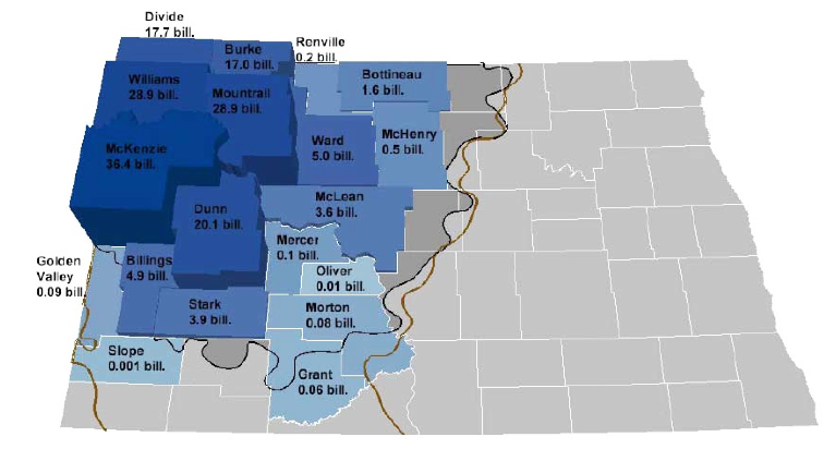
OOIP estimates by county (North Dakota DMR)
The state has also produced some three-dimensional models of the formations in the region around Williston, which is where some of the most productive wells are found.
Region of North Dakota that is modeled. (ND DMR ) The sides of the square cover 135 miles.
By developing the model it is possible to look both at the section showing the location of the productive beds in the region. Since the Department covers other valuable minerals beside oil and gas, they are also shown in the section:
Section through the ND geology (ND DMR )
The Bakken lies at a depth of around 11,500 ft with the additional need for rigs to drill 20,000 ft coming from the use of horizontal drilling along the formation, which is typically only around 150 ft thick. One of the advantage of the model is that it can be used to generate a view of the Bakken itself, with the overlying ground removed. This also helps show that, while the above section shows the beds lying in a syncline, where oil might be expected to migrate out and up the sides away from the central dip, there is a central anticline where oil could be trapped, and the structure is not smooth. (Bear in mind also the scale of the model, so that small traps in the field are not picked up at this level. ) The structure of the shale beds themselves also make it less sensitive to geological modifications which drive oil migration, though obviously not completely or else there would be little oil flow to the well.
Model of the Bakken formation around Williston (ND DMR )
The dominant feature that runs relatively North-South through the center helps then explain the location of many wells drilling into the reservoir.
L:ocation of wells in the modeled region of North Dakota (ND DMR )
While the formations have been known for some time it was only with the development of horizontal wells, and fracking capabilities, that the opportunities to extract the oil became viable. To borrow a picture from that earlier post by Piccolo (H/t Gail)
Change in Bakken production with the introduction of horizontal wells and Fracing (TOD)
As the number of horizontal wells has grown one finds, as I noted above, that 20,000 ft of drilling will include perhaps 9,000 ft of horizontal well in the formation itself. Such a well, as for example the Credo Petroleum well that is cited, may initially produce 1,267 bd of oil and 1.24 mcf/day of natural gas.
However one of the concerns that has been expressed, both by Art Berman, and later myself, has to do with the long-term production rate from long horizontal, frac’ed wells in shale, and it is therefore instructive to see the information that is now available on a typical well, which has been compiled by the ND DMR.
Typical Bakken well production (ND DMR )
At the time of the presentation (last year) there was still a large proportion of the gas being flared.
Gas flared as a percentage in ND (ND DMR )
Since then, as I noted at the start of the piece, the amount flared in May of this year has risen to 29%.
There is a more than adequate array of pipelines to handle the fuel that is being produced, at the moment it is the oil that is the critical, and valuable component. But even with a projection that the state will see about 2,000 wells a year being drilled over the next few years, with the expectation that the field will last some 20 years, the overall production is not expected to increase much beyond the levels that it is now attaining. This is because of the relatively rapid drop in well production, for which there is now a considerable data base. That doesn’t stop some from projecting, however, that the field can increase in production to levels as high as 1 mbd or so. That would, of course, include production from Montana and Canadian parts of the Bakken, which I have not discussed here.
One point that should be noted is that the lease rates for Bakken in North Dakota are quoted as being around $7,000 to $8,000 per acre, while those in Montana are reported to be considerably less. To date there has not been that much activity in Montana, though with time this will change. Already permit numbers are rising, and there has been some success to equal that in North Dakota.
At present, however, most of the rigs (170 to 10) remain on the North Dakota side of the border. That too will change, with time.
Overall the Bakken is likely to see further increases in production as the areas being drilled expand, but with the relatively short life of the well at significant levels of production, it is harder to see the higher levels of production overall that others have cited, and one also has to remember that is often the sweetest spots that get drilled first.
North Dakota Shallow gas exploration is not economic at the current price.The answer lies in the Bakken and Three Forks with rigs that can drill more than 20,000 ft being the most actively employed. The Bakken has already been discussed in an earlier post at The Oil Drum and I don’t really want to repeat much of that information, and so this presentation will, perhaps, rely a little more on visuals. The Bakken and Three Forks partially lie in Western North Dakota, and the Department of Mineral Resources (DMR) for the state, has shown how the total Original Oil In Place (OOIP) estimates vary from county to county within that region.
OOIP estimates by county (North Dakota DMR)
The state has also produced some three-dimensional models of the formations in the region around Williston, which is where some of the most productive wells are found.
Region of North Dakota that is modeled. (ND DMR ) The sides of the square cover 135 miles.
By developing the model it is possible to look both at the section showing the location of the productive beds in the region. Since the Department covers other valuable minerals beside oil and gas, they are also shown in the section:
Section through the ND geology (ND DMR )
The Bakken lies at a depth of around 11,500 ft with the additional need for rigs to drill 20,000 ft coming from the use of horizontal drilling along the formation, which is typically only around 150 ft thick. One of the advantage of the model is that it can be used to generate a view of the Bakken itself, with the overlying ground removed. This also helps show that, while the above section shows the beds lying in a syncline, where oil might be expected to migrate out and up the sides away from the central dip, there is a central anticline where oil could be trapped, and the structure is not smooth. (Bear in mind also the scale of the model, so that small traps in the field are not picked up at this level. ) The structure of the shale beds themselves also make it less sensitive to geological modifications which drive oil migration, though obviously not completely or else there would be little oil flow to the well.
Model of the Bakken formation around Williston (ND DMR )
The dominant feature that runs relatively North-South through the center helps then explain the location of many wells drilling into the reservoir.
L:ocation of wells in the modeled region of North Dakota (ND DMR )
While the formations have been known for some time it was only with the development of horizontal wells, and fracking capabilities, that the opportunities to extract the oil became viable. To borrow a picture from that earlier post by Piccolo (H/t Gail)
Change in Bakken production with the introduction of horizontal wells and Fracing (TOD)
As the number of horizontal wells has grown one finds, as I noted above, that 20,000 ft of drilling will include perhaps 9,000 ft of horizontal well in the formation itself. Such a well, as for example the Credo Petroleum well that is cited, may initially produce 1,267 bd of oil and 1.24 mcf/day of natural gas.
However one of the concerns that has been expressed, both by Art Berman, and later myself, has to do with the long-term production rate from long horizontal, frac’ed wells in shale, and it is therefore instructive to see the information that is now available on a typical well, which has been compiled by the ND DMR.
Typical Bakken well production (ND DMR )
At the time of the presentation (last year) there was still a large proportion of the gas being flared.
Gas flared as a percentage in ND (ND DMR )
Since then, as I noted at the start of the piece, the amount flared in May of this year has risen to 29%.
There is a more than adequate array of pipelines to handle the fuel that is being produced, at the moment it is the oil that is the critical, and valuable component. But even with a projection that the state will see about 2,000 wells a year being drilled over the next few years, with the expectation that the field will last some 20 years, the overall production is not expected to increase much beyond the levels that it is now attaining. This is because of the relatively rapid drop in well production, for which there is now a considerable data base. That doesn’t stop some from projecting, however, that the field can increase in production to levels as high as 1 mbd or so. That would, of course, include production from Montana and Canadian parts of the Bakken, which I have not discussed here.
One point that should be noted is that the lease rates for Bakken in North Dakota are quoted as being around $7,000 to $8,000 per acre, while those in Montana are reported to be considerably less. To date there has not been that much activity in Montana, though with time this will change. Already permit numbers are rising, and there has been some success to equal that in North Dakota.
Brigham Exploration, one of the most aggressive in Montana, recently unveiled five wells there ranging from 909 boe/d to 2,962 boe/d, the latter volume a "record for the state," Pritchard said. The five wells averaged 1,579 boe/d.
At present, however, most of the rigs (170 to 10) remain on the North Dakota side of the border. That too will change, with time.
Overall the Bakken is likely to see further increases in production as the areas being drilled expand, but with the relatively short life of the well at significant levels of production, it is harder to see the higher levels of production overall that others have cited, and one also has to remember that is often the sweetest spots that get drilled first.
Read more!
Labels:
Bakken,
gas shales,
horizontal wells,
Montana,
North Dakota,
Three Forks
Wednesday, November 17, 2010
Me, This Week in Energy, and why Halliburton might refuse EPA
This afternoon I was an invited guest on “This Week in Energy” with Nikki Gordon-Bloomfield and Bob Tregelus. Among other things we talked about the fracking process that is being used to help produce the natural gas from shales such as the Marcellus and Haynesville. In the course of the discussion I was asked why of the nine fracking companies that EPA asked for their formulae, only Halliburton had refused the request. Bob pointed out that they were going to be subpoenaed and thus would have to give up the information anyway. I have discussed some of the problems of stimulating a well with hydraulic fracturing, both real and less so, on this site last March when the public perception of the technology began to change.
In the possible explanation I am going to give, you need to know that this is purely a supposition and the chemicals that I am going to mention are put forward out of my own head, as it were. I have no real clue as to why Halliburton are acting the way that they are, and am only building a hypothesis that might only through some slight possibility have any approximate relation to the truth.
In the evolution of the technology that has made production of the gas shales possible several different technologies had to be developed. The rock (which is actually a mudstone) has a very poor natural permeability. I.e. it is very difficult for fluid to flow through the rock, because the passage ways are very narrow and not very well connected. Thus the normal vertical wells would not produce very much oil or gas when drilled through the shale reservoir, certainly not enough to be profitable. The first beneficial development was, therefore, the ability to drill horizontally after the well had reached the reservoir depth. Once this was possible, then the length of the well that was exposed to the reservoir (which might be only 30 ft thick) would increase from that 30 ft to perhaps 10,000 ft. Since the amount of fluid flowing into the well is a function of the length of the exposed well in the rock, when the reservoir rock has a normal permeability this is enough to increase production significantly (as for example in the new wells in Saudi Arabia).
However when the rock has a very poor permeability even the long wells will only very slowly accumulate fluid from the surrounding rock, since there are no easy passages to the well through that rock. Thus the next benefit that was needed was the ability to crack the rock around the well. This is known as hydraulic fracturing or hydrofracking for short. In modern wells, by isolating and then pressurizing different segments of the well in turn, these cracks can be created (when the pressure inside the well exceeds the rock strength) at regular intervals (say 30 to 120 ft apart) along the length of the borehole.
The cracks are controlled in length (since if they go outside the reservoir all the fluid can drain away through the other end of the cracks, not to the well). But the problem is that once the crack is made, the pressure inside the well is lowered and the equipment moved to the next segment. Without any other changes as the pressure comes off the crack it will close back up, and there will not be much gain from the effort. So to keep the crack open what the industry calls a proppant, but you or I might just call it a carefully sized sand, is mixed with the fracking fluid before it is injected into the well.
As a result, when the cracks open in the rock, and the fracking fluid flows into the crack, the sand is carried with it, and is then trapped in the crack, holding it open after the pressure is lowered. A passage then exists for the gas or oil to travel to the well and production of most of the rock volume becomes possible.
Well that was when the development of the gas shale deposits began, however it had not been going on very long when it was noticed that the sand was not flowing easily into the fractures, and without enough sand being carried far enough back into the cracks, production wasn’t nearly as good as it should have been.
At this point another development was needed. This came about when an additional chemical – what is known as a long-chain polymer (typically a polyacrylamide) - was added to the fracking fluid. These fluids are known as Friction Reducing Agents (FRAs) because they tend to make water stick together a bit, and create extremely slippery surfaces when they coat them. By adding these FRAs to the fracking fluid, the crack walls became slipperier and the sand particles could thus travel deeper into the cracks, holding them open more effectively and increasing gas production. The fluids were given the generic name “slick water”, so that the current state-of-the-art is a horizontal well that has had a multi-fracture, slickwater-hydrofracking operation run on it.
But the problems of the wells are not over. As I noted in my post yesterday, the mudstones contain a significant amount of clays. And the problem when clays get wet is that they get softer and clay particles can break away from the wall of the fracture (slaking). Over the different gas shale deposits the problems are not consistent, since each shale is made of a different set of constituent rock types and clays. But overall the problem that is now being evidenced, as Art Berman has commented a number of times, is that the wells are losing production faster and earlier than predicted, so that they cannot meet the overall targets that make the well profitable. Instead of the well lasting perhaps a decade, they are losing perhaps 60% of the flow in the first year, and are no longer worth operating after maybe three years.
With all that as background, here is a hypothesis to explain Halliburton’s actions. It is quite possible that the well failures are due to the clay failure in the shale reducing the crack effectiveness. Clay content failure can do this, once the fracking fluid has cracked and wetted it, by a long term softening (which will allow the walls of the crack to fold around the proppant particles, and close the crack as the walls move in), or simply swelling into some of the crack space, with the same effect. Alternately the clay particles may slake and break away from the walls of the crack, and over time build up small dams along the crack path, again blocking the fluid flow through the crack – any one of these mechanisms explains the production falls that are being seen in the industry.
So lets say that Halliburton has realized the problem and, for merely the sake of a discussable solution, changes the polymer that they use from a pure polyacrylamide (PA) to include polyethylene oxide (PO). One thing that PO does at much lower concentrations than PA is that it stops the fracking fluid from wetting the shale, and interacting with the clay. Because it is (or at least was when we did this) much more expensive than PA there is not normally any reason to use PO in the fracking fluid.
But let us say that Halliburton have tried this, and it works. Because it is a step change in the process (in the same way as horizontal drilling; fracking; and slick water use were each, in turn) then the company selling the new idea has a tremendous commercial advantage. They can promise you that your well will stay in production long enough for you to make a profit, while the competition cannot.
The world of hydrofracking contractors is small and engineers move around, so that commercial advantage does not last very long, and word gets out as to how it was done. But that takes time, first to find out what is causing the problem, then what the answer is in general, and then what the answer is in detail. Each of those steps might take a competitor a year. That gives you three years of advantage, when you can charge higher rates, and possibly put some of that competition out of business.
The problem is that if the competition sees that you have put PO in your fluid, instead of PA then they can immediately go and look up what difference that makes to the fluid. Knowing that it stops wetting immediately gets them past stages one and two and cuts the term of your commercial advantage from three years to one.
Would you want to give that up if, by lawyering and all those fancy tricks they get up to in Washington you could get the time that you have to release the content postponed by at least a year? Likely not, and since dragging out the process can extend the period of your commercial advantage, the longer you can keep kicking the ball down the street the greater your advantage, and the more benefit.
And I re-iterate this is purely a hypothesis that I came up with, and I have no connections that would suggest that this has any connection to reality.
In the possible explanation I am going to give, you need to know that this is purely a supposition and the chemicals that I am going to mention are put forward out of my own head, as it were. I have no real clue as to why Halliburton are acting the way that they are, and am only building a hypothesis that might only through some slight possibility have any approximate relation to the truth.
In the evolution of the technology that has made production of the gas shales possible several different technologies had to be developed. The rock (which is actually a mudstone) has a very poor natural permeability. I.e. it is very difficult for fluid to flow through the rock, because the passage ways are very narrow and not very well connected. Thus the normal vertical wells would not produce very much oil or gas when drilled through the shale reservoir, certainly not enough to be profitable. The first beneficial development was, therefore, the ability to drill horizontally after the well had reached the reservoir depth. Once this was possible, then the length of the well that was exposed to the reservoir (which might be only 30 ft thick) would increase from that 30 ft to perhaps 10,000 ft. Since the amount of fluid flowing into the well is a function of the length of the exposed well in the rock, when the reservoir rock has a normal permeability this is enough to increase production significantly (as for example in the new wells in Saudi Arabia).
However when the rock has a very poor permeability even the long wells will only very slowly accumulate fluid from the surrounding rock, since there are no easy passages to the well through that rock. Thus the next benefit that was needed was the ability to crack the rock around the well. This is known as hydraulic fracturing or hydrofracking for short. In modern wells, by isolating and then pressurizing different segments of the well in turn, these cracks can be created (when the pressure inside the well exceeds the rock strength) at regular intervals (say 30 to 120 ft apart) along the length of the borehole.
The cracks are controlled in length (since if they go outside the reservoir all the fluid can drain away through the other end of the cracks, not to the well). But the problem is that once the crack is made, the pressure inside the well is lowered and the equipment moved to the next segment. Without any other changes as the pressure comes off the crack it will close back up, and there will not be much gain from the effort. So to keep the crack open what the industry calls a proppant, but you or I might just call it a carefully sized sand, is mixed with the fracking fluid before it is injected into the well.
As a result, when the cracks open in the rock, and the fracking fluid flows into the crack, the sand is carried with it, and is then trapped in the crack, holding it open after the pressure is lowered. A passage then exists for the gas or oil to travel to the well and production of most of the rock volume becomes possible.
Well that was when the development of the gas shale deposits began, however it had not been going on very long when it was noticed that the sand was not flowing easily into the fractures, and without enough sand being carried far enough back into the cracks, production wasn’t nearly as good as it should have been.
At this point another development was needed. This came about when an additional chemical – what is known as a long-chain polymer (typically a polyacrylamide) - was added to the fracking fluid. These fluids are known as Friction Reducing Agents (FRAs) because they tend to make water stick together a bit, and create extremely slippery surfaces when they coat them. By adding these FRAs to the fracking fluid, the crack walls became slipperier and the sand particles could thus travel deeper into the cracks, holding them open more effectively and increasing gas production. The fluids were given the generic name “slick water”, so that the current state-of-the-art is a horizontal well that has had a multi-fracture, slickwater-hydrofracking operation run on it.
But the problems of the wells are not over. As I noted in my post yesterday, the mudstones contain a significant amount of clays. And the problem when clays get wet is that they get softer and clay particles can break away from the wall of the fracture (slaking). Over the different gas shale deposits the problems are not consistent, since each shale is made of a different set of constituent rock types and clays. But overall the problem that is now being evidenced, as Art Berman has commented a number of times, is that the wells are losing production faster and earlier than predicted, so that they cannot meet the overall targets that make the well profitable. Instead of the well lasting perhaps a decade, they are losing perhaps 60% of the flow in the first year, and are no longer worth operating after maybe three years.
With all that as background, here is a hypothesis to explain Halliburton’s actions. It is quite possible that the well failures are due to the clay failure in the shale reducing the crack effectiveness. Clay content failure can do this, once the fracking fluid has cracked and wetted it, by a long term softening (which will allow the walls of the crack to fold around the proppant particles, and close the crack as the walls move in), or simply swelling into some of the crack space, with the same effect. Alternately the clay particles may slake and break away from the walls of the crack, and over time build up small dams along the crack path, again blocking the fluid flow through the crack – any one of these mechanisms explains the production falls that are being seen in the industry.
So lets say that Halliburton has realized the problem and, for merely the sake of a discussable solution, changes the polymer that they use from a pure polyacrylamide (PA) to include polyethylene oxide (PO). One thing that PO does at much lower concentrations than PA is that it stops the fracking fluid from wetting the shale, and interacting with the clay. Because it is (or at least was when we did this) much more expensive than PA there is not normally any reason to use PO in the fracking fluid.
But let us say that Halliburton have tried this, and it works. Because it is a step change in the process (in the same way as horizontal drilling; fracking; and slick water use were each, in turn) then the company selling the new idea has a tremendous commercial advantage. They can promise you that your well will stay in production long enough for you to make a profit, while the competition cannot.
The world of hydrofracking contractors is small and engineers move around, so that commercial advantage does not last very long, and word gets out as to how it was done. But that takes time, first to find out what is causing the problem, then what the answer is in general, and then what the answer is in detail. Each of those steps might take a competitor a year. That gives you three years of advantage, when you can charge higher rates, and possibly put some of that competition out of business.
The problem is that if the competition sees that you have put PO in your fluid, instead of PA then they can immediately go and look up what difference that makes to the fluid. Knowing that it stops wetting immediately gets them past stages one and two and cuts the term of your commercial advantage from three years to one.
Would you want to give that up if, by lawyering and all those fancy tricks they get up to in Washington you could get the time that you have to release the content postponed by at least a year? Likely not, and since dragging out the process can extend the period of your commercial advantage, the longer you can keep kicking the ball down the street the greater your advantage, and the more benefit.
And I re-iterate this is purely a hypothesis that I came up with, and I have no connections that would suggest that this has any connection to reality.
Read more!
Sunday, November 15, 2009
Making holes and cracks around oil and gas wells
This is a continuation of the technical topics that I write about on Sundays. For the past few weeks I have been writing about some of the techniques used in producing the gas from shales, and that will likely continue for another week or two. Because of the need to condense the topic into a relatively short post I would ask those familiar with the topics to understand that I have had to shorten the description and gloss over some details in order to keep the main theme clear. But further comments to help readers understand the techniques better (or questions when it isn't) are appreciated.
There is a simple test that I use in one of my introductory classes, where I give the students a rectangle of paper and ask them to pull it apart, then I give them a rectangle with a cut half way through it perpendicular to the length, and half-way down, and ask them to pull that apart. It tears apart much more easily, and it is how I start a lecture on the role of cracks in causing materials to fail. You apply that principle about every time you pull open a package with a serrated top. The deeper cuts focus the force you are pulling with over a small area, making it easier to part the package and extract the candy, nuts or whatever without having to pull so hard that, when the package tears, you throw the contents around the neighborhood.
Today I want to talk a little more about perforating the wall of a well, and a bit more about hydrofracing. They are not necessarily used together, but both are ways of getting cracks out from the immediate wall of the wellbore so that the valuable fluid on the other side can have an easier path into the well.
To begin with the topic of perforating a well, I have written about this earlier, but more from the point of the tools used to do the job. What I’d like to do here is to talk a little more about it from the rock point of view. As I mentioned last time the rock right around the well can be subject to a high enough pressure that it will partially fail, or crush, and this can lower the amount of fluid that can get through, or alternately it might have been damaged in some other way. By bringing in a tool with a set of shaped charges in it, and then firing these at the appropriate place this problem can be overcome.
Arrangement of shaped charges (the yellow cylinders) – when the explosive goes off the cones collapse and small liquid metal jets shoot out of the open end, through the casing, concrete and into the rock, creating a channel. (Core Labs)
The charges aren’t all necessarily fired at one time or place, even though, for the illustration below, they appear to be.
Representation of shaped charges firing and penetrating the casing, cement and wall (OSHA
The jet of metal that shoots out of the cone will travel into the rock roughly 10 cone diameters, as a rough rule of thumb, and this carries a channel, or tunnel, out through the damaged rock into the surrounding reservoir. The collapse and creation of the channel happens very fast:
Penetration of a perforating charge into Plexiglas after 3, 12, 21 and 30 microseconds. Marks are in cone diameters. (after Konya*)
The channel is initially hollow, and drives a set of small and large cracks out into the rock around the line of the charge.
Jet penetration through Plexiglas (note the lateral cracks away from the line of penetration. The dark section is due to a change in background. (after Konya*)
However, while it is easier to show the damage that the jet does by showing how it penetrates Plexiglas, this is not rock, but it does show some of the events that occur. When, for example, (vide the discussion on jointed shale last week) the jet shoots into rock where there are clear joint planes defined, then these act to stop the crack growth (perhaps in the way that those who used to remember stopping cracks growing in old cars by drilling a hole at the end of the crack. It distributes the stress that was causing the crack to grow when focused on the tip, over a larger area so that it drops below the critical level). Or the stress is high enough to cause cracks to form and be reflected back at the jet.
Jet damage confined between two adjacent planes when the charge is fired into plates that run parallel to the direction of the jet. (after Konya*)
If the charge is not carefully designed and used, therefore, it might not be as effective as initially hoped, and this becomes even more true if the pieces of metal that are formed when the cone collapses are carried into the channel and partially block it. There are different strategies, depending on the well and the surrounding rock and it is one of those things in life where, if you got it right the results are almost immediately obvious – as is the converse.
Creating cracks that go out into the surrounding rock has become a vital part of the economic production of gas from the shales around the country, as we have discussed, and having a starting crack in the right direction, whether it is a natural joint in the rock, or a crack that has been deliberately created helps control where the crack starts and how it grows.
Crack growing out from a drilled hole in Plexiglas, the small notch at the top of the hole controlled the direction of the growth of the crack (We put ink in the hole to show how the fluid goes into the crack).
In the above picture you can see that when the hole was pressurized, a crack grew, and ink flowed into the crack, as it formed, but, when the pressure came off, the crack closed and most of the ink was forced back out of the crack. (We created the pressure by firing an air rifle pellet into the hole).
So if we are going to have a useful crack we need to have it open after we take the pressure back off – after all we need to get the fluid back out of the well, so that the gas can pass up the well for collection.
Now it is not quite as easy to grow the crack, or prop it open as I may have suggested earlier, and to explain some of the issues in a little more detail I am going to use an example and some details from the Modern Shale Gas Primer .
When you decide to frac the well, and each well is different, as is just about every location, so there is a significant amount of preparation and knowledge required to work out the procedure required at that particular point. Bear in mind that the crack that you are going to have to grow needs to stay in the shale layer, and not go out beyond it into the surrounding rock. One of the reasons for this is, apart from giving the gas a path to the well, if it goes outside the reservoir rock then the gas can escape, or, alternately, other fluids can gain access to the well. This is particularly true of the Barnett where the rock immediately below it, the Ellenberger limestones, can hold a lot of water that can muck up the gas recovery if it gets into the fractures. (Given this degree of control and the large distance below the ground to the reservoir rock, this is why a lot of the fears that the frac job will damage the ground water tend to be dramatically overstated).
In the example cited, which is from the Marcellus shale, the treatment of the frac takes a total of 18 steps, and because some of these are fairly similar I am going to go through them in groups. First the hole is treated with an acid, to clean away any remaining debris and mud from the drilling operation and to clean any fractures around the hole, so that they can be used to help the frac grow. After the acid the hole is filled with an initial polymeric fluid, largely water, but containing the “Banana Water” that I referred to in an earlier post. This is a friction reducing agent and will help carry the particles used to hold the crack open into the crack in the first place. The problem with that polymer is that some of the choices available, while good at reducing the friction to help move the particles, aren’t that good at holding the particles in suspension, and the last thing we need is for them to settle out in the bottom of the well, and so in the subsequent steps in the process as the particles (or proppants) are added, there is usually a second polymer in the mix to hold them in suspension.
Once the hole is full of the slickwater (the official term for the first polymer solution) the initial frac is made with a fine sand suspended in the fluid. To keep the crack open all along its length we need sand along the path and the crack gets narrower as it grows deeper. So for the first several stages of the crack growth the fluid is filled with successively greater concentrations of the fine sand, so that, in this way, it can penetrate to the deepest part of the fracture.
In the example cited there are some seven of these sub-stages with the fluid being pumped into the well at some 3,000 gpm but varying the fluid:proppant density to carry more and more of the particles into the fracture. Once these stages have been completed, then the job is finished by pumping an additional eight sub-stages of fluid, with this second set containing a larger size of proppant particles. In this way the area closest to the mouth of the fracture will be held wider apart to make it easier for the gas to escape. As with the first set of sub-stages, the concentration of proppant in the fluid increases as the stages progress. In total, in the example given, some 450,000 lb of proppant was used to make the fracture, together with some 578,000 gallons of water.
Once the fracture is created, then the well is flushed to clean out the different fluids, and make it easier for the gas to get out out of the rock and into the well. (It also removes any loose and ineffective proppant so that it doesn’t later become a nuisance). If you think that this would need a lot of equipment you are right!
Equipment used for hydraulic fracturing a well (Primer)
Since there is some discussion of the effects of the different constituents of the fracing fluid on local waters I thought I would end with the listing of common chemicals used in that liquid, which is provided in the Primer .
As usual this has had to be a very brief review of the technology and may have oversimplified to the point of not being clear, so all technical comments and questions are appreciated.


* The initial photos in this post were taken as part of the dissertation of Dr Konya, "The use of Shaped Explosive Charges to Investigate Permeability, Penetration and Fracture Formation in Coal, Dolomite and Plexiglas" Missouri S&T, 1972.
There is a simple test that I use in one of my introductory classes, where I give the students a rectangle of paper and ask them to pull it apart, then I give them a rectangle with a cut half way through it perpendicular to the length, and half-way down, and ask them to pull that apart. It tears apart much more easily, and it is how I start a lecture on the role of cracks in causing materials to fail. You apply that principle about every time you pull open a package with a serrated top. The deeper cuts focus the force you are pulling with over a small area, making it easier to part the package and extract the candy, nuts or whatever without having to pull so hard that, when the package tears, you throw the contents around the neighborhood.
Today I want to talk a little more about perforating the wall of a well, and a bit more about hydrofracing. They are not necessarily used together, but both are ways of getting cracks out from the immediate wall of the wellbore so that the valuable fluid on the other side can have an easier path into the well.
To begin with the topic of perforating a well, I have written about this earlier, but more from the point of the tools used to do the job. What I’d like to do here is to talk a little more about it from the rock point of view. As I mentioned last time the rock right around the well can be subject to a high enough pressure that it will partially fail, or crush, and this can lower the amount of fluid that can get through, or alternately it might have been damaged in some other way. By bringing in a tool with a set of shaped charges in it, and then firing these at the appropriate place this problem can be overcome.
Arrangement of shaped charges (the yellow cylinders) – when the explosive goes off the cones collapse and small liquid metal jets shoot out of the open end, through the casing, concrete and into the rock, creating a channel. (Core Labs)The charges aren’t all necessarily fired at one time or place, even though, for the illustration below, they appear to be.
Representation of shaped charges firing and penetrating the casing, cement and wall (OSHAThe jet of metal that shoots out of the cone will travel into the rock roughly 10 cone diameters, as a rough rule of thumb, and this carries a channel, or tunnel, out through the damaged rock into the surrounding reservoir. The collapse and creation of the channel happens very fast:
Penetration of a perforating charge into Plexiglas after 3, 12, 21 and 30 microseconds. Marks are in cone diameters. (after Konya*)The channel is initially hollow, and drives a set of small and large cracks out into the rock around the line of the charge.
Jet penetration through Plexiglas (note the lateral cracks away from the line of penetration. The dark section is due to a change in background. (after Konya*)However, while it is easier to show the damage that the jet does by showing how it penetrates Plexiglas, this is not rock, but it does show some of the events that occur. When, for example, (vide the discussion on jointed shale last week) the jet shoots into rock where there are clear joint planes defined, then these act to stop the crack growth (perhaps in the way that those who used to remember stopping cracks growing in old cars by drilling a hole at the end of the crack. It distributes the stress that was causing the crack to grow when focused on the tip, over a larger area so that it drops below the critical level). Or the stress is high enough to cause cracks to form and be reflected back at the jet.
Jet damage confined between two adjacent planes when the charge is fired into plates that run parallel to the direction of the jet. (after Konya*)If the charge is not carefully designed and used, therefore, it might not be as effective as initially hoped, and this becomes even more true if the pieces of metal that are formed when the cone collapses are carried into the channel and partially block it. There are different strategies, depending on the well and the surrounding rock and it is one of those things in life where, if you got it right the results are almost immediately obvious – as is the converse.
Creating cracks that go out into the surrounding rock has become a vital part of the economic production of gas from the shales around the country, as we have discussed, and having a starting crack in the right direction, whether it is a natural joint in the rock, or a crack that has been deliberately created helps control where the crack starts and how it grows.
In the above picture you can see that when the hole was pressurized, a crack grew, and ink flowed into the crack, as it formed, but, when the pressure came off, the crack closed and most of the ink was forced back out of the crack. (We created the pressure by firing an air rifle pellet into the hole).
So if we are going to have a useful crack we need to have it open after we take the pressure back off – after all we need to get the fluid back out of the well, so that the gas can pass up the well for collection.
Now it is not quite as easy to grow the crack, or prop it open as I may have suggested earlier, and to explain some of the issues in a little more detail I am going to use an example and some details from the Modern Shale Gas Primer .
When you decide to frac the well, and each well is different, as is just about every location, so there is a significant amount of preparation and knowledge required to work out the procedure required at that particular point. Bear in mind that the crack that you are going to have to grow needs to stay in the shale layer, and not go out beyond it into the surrounding rock. One of the reasons for this is, apart from giving the gas a path to the well, if it goes outside the reservoir rock then the gas can escape, or, alternately, other fluids can gain access to the well. This is particularly true of the Barnett where the rock immediately below it, the Ellenberger limestones, can hold a lot of water that can muck up the gas recovery if it gets into the fractures. (Given this degree of control and the large distance below the ground to the reservoir rock, this is why a lot of the fears that the frac job will damage the ground water tend to be dramatically overstated).
In the example cited, which is from the Marcellus shale, the treatment of the frac takes a total of 18 steps, and because some of these are fairly similar I am going to go through them in groups. First the hole is treated with an acid, to clean away any remaining debris and mud from the drilling operation and to clean any fractures around the hole, so that they can be used to help the frac grow. After the acid the hole is filled with an initial polymeric fluid, largely water, but containing the “Banana Water” that I referred to in an earlier post. This is a friction reducing agent and will help carry the particles used to hold the crack open into the crack in the first place. The problem with that polymer is that some of the choices available, while good at reducing the friction to help move the particles, aren’t that good at holding the particles in suspension, and the last thing we need is for them to settle out in the bottom of the well, and so in the subsequent steps in the process as the particles (or proppants) are added, there is usually a second polymer in the mix to hold them in suspension.
Once the hole is full of the slickwater (the official term for the first polymer solution) the initial frac is made with a fine sand suspended in the fluid. To keep the crack open all along its length we need sand along the path and the crack gets narrower as it grows deeper. So for the first several stages of the crack growth the fluid is filled with successively greater concentrations of the fine sand, so that, in this way, it can penetrate to the deepest part of the fracture.
In the example cited there are some seven of these sub-stages with the fluid being pumped into the well at some 3,000 gpm but varying the fluid:proppant density to carry more and more of the particles into the fracture. Once these stages have been completed, then the job is finished by pumping an additional eight sub-stages of fluid, with this second set containing a larger size of proppant particles. In this way the area closest to the mouth of the fracture will be held wider apart to make it easier for the gas to escape. As with the first set of sub-stages, the concentration of proppant in the fluid increases as the stages progress. In total, in the example given, some 450,000 lb of proppant was used to make the fracture, together with some 578,000 gallons of water.
Once the fracture is created, then the well is flushed to clean out the different fluids, and make it easier for the gas to get out out of the rock and into the well. (It also removes any loose and ineffective proppant so that it doesn’t later become a nuisance). If you think that this would need a lot of equipment you are right!
Equipment used for hydraulic fracturing a well (Primer)Since there is some discussion of the effects of the different constituents of the fracing fluid on local waters I thought I would end with the listing of common chemicals used in that liquid, which is provided in the Primer .
As usual this has had to be a very brief review of the technology and may have oversimplified to the point of not being clear, so all technical comments and questions are appreciated.


* The initial photos in this post were taken as part of the dissertation of Dr Konya, "The use of Shaped Explosive Charges to Investigate Permeability, Penetration and Fracture Formation in Coal, Dolomite and Plexiglas" Missouri S&T, 1972.
Read more!
Sunday, November 8, 2009
Horizontal wells and Gas Shales
This post is one in a series, describing some of the ways in which fossil fuels are produced, and in the current part of the series (listed on the right hand side of the site – you should start at the bottom and work up) we are focusing a little more on the procedures that are being used to recover natural gas from formations such as the Barnett, Fayetteville, Marcellus, Haynesville and Woodford shales. In this particular post I am going to concentrate more on the benefits of horizontal drilling through these shale reservoirs, rather than using the more conventional vertical wells that were used historically. This, and the next three posts in the series are likely to be a bit more technically dense than earlier posts but I am trying to illustrate some of the problems of production, and some of the gains that technology is bringing to help solve some of them. And while the reason for the horizontal wells can be simplified in this graph from Chris McGill, there are a lot of other things that have to be considered in deciding whether or not the horizontal well is going to be worth developing.

Comparative production from a vertical and horizontal natural gas well (Chris McGill). Notice the gain in production, but much shorter life of the horizontal well.
To begin with it’s probably best to start with rock pressure. And to explain this I am going to do some simplification, so, as I ask in most of these “techie talks”, to those who do know better please understand that this is trying to explain concepts, but also please do comment on where I may either accidentally or by error, get something wrong. I am also going to repeat some information from earlier posts, since some of you may not have read them.
As we go deeper into the earth, the weight of the ground above us will also increase. For a very simple measure (and to make the illustrations easier to follow) we can assume that this is around a 1 pound per square inch (psi) increase for every foot deeper we go. So if we were, for example, 10,000 ft down then the pressure in the rock due to that weight would, undisturbed, be around 10,000 psi. (This is about 7 times the pressure that you see coming out of a car wash pressure washer for example).
When a oilwell is drilled vertically down into that rock it does not see this pressure, but it does see a part of it. The reason is that the rock on either side of the hole can now expand into the hole, and we’d rather it didn’t. (It’s somewhat as though you step on a rubber eraser – the eraser will bulge out laterally as it compresses vertically under your weight). The resistant pressure in the horizontal direction can be calculated as a function of the vertical pressure through a ratio known as Poisson’s Ratio. Sufficient for our discussion to say that it can have a value of about 0.3. So that if we are 10,000 ft down, then the vertical pressure on the rock will be around 10,000 psi, and the horizontal pressure will be around 3,000 psi. If the well is vertical then the casing for the well may not have to resist pressures of more than the 3,000 psi level.
Now, if instead of just drilling the well vertically I turned and drilled it out horizontally through the rock, then the hole would now have the 10,000 psi squeezing down vertically, and the 3,000 psi coming in from the side. So the first thought that we have is that the casing (the lining that we put into the hole to make sure that it stays open) has to be a bit stronger. Life gets, however, a bit more complicated than that. When you put a hole into ground that is under pressure, the first response of the rock is to try and move the weight of the rock over the hole onto the rock on the sides of the hole. This roughly doubles the pressure that is on that thin layer. Before the hole was put there that particular rock was held in place by the rock around it, and collectively the mass could carry the original pressure. But now there is no rock where the hole is, and thus the confining pressure on the rock there is less. (In technical terms you have shifted the load from a triaxial confinement under 10,000 psi to a uniaxial load of 20,000 psi. if there was no pressure within the well). The result can be that the rock on the sides of the hole crushes under the load. This then puts crushed rock or sand into the hole, and that interferes with lots of things. Now you can possibly stop that by keeping the pressure high in the liquid that you are using inside the hole to get the drilled rock out (the drilling mud), but if you keep that pressure too high, then the oil/gas won’t flow to the well and so you have to drop it down to a certain level by choking the flow out of the well when, after completing the hole, you go back to start production.
Life also gets a bit more complicated in reality, since the presence of the fluid in the rock tends to even out the pressure within it. So that while, relatively close to the surface, and in a dry rock the ratios may be as I gave them earlier, with a fluid saturated rock, and in an over-pressured region, the horizontal pressure can be as high as 80% or more of the vertical value. The values generally get closer to 100% as the wells go even deeper, but that is another story.
So rock pressure is the first problem that you have to deal with. But why do we drill the horizontal holes in the first place, why can’t we just use the old vertical ones. Well the reason is that the old ones didn’t work very well. And to explain that I am gong to try and re-explain an article from Penn State. (then I’ll give the relevant quote).
Shale is a very fine grained rock, and though gas can gather in the small pores of its structure, if the gas is to flow to a well, then it has to migrate through passages that are very narrow, and thus very resistive to that flow. However, as the shale has been formed under geological pressure and over time, the pressures not only compressed it from mud into shale, but they also caused it to fracture. In the Marcellus shale, for example, the cracks that occurred in the shale are roughly vertical, and form two sets that are perpendicular to one another.
The first advantage that a horizontal well has, over a vertical one, is that the well can penetrate a long way through the rock that carries the oil or gas (OG). The amount of OG that comes from the rock is, in part, a function of how long the length of well is in the rock that carries it. So that while a vertical well might produce say 800 bd from a well that goes straight through a 200 ft thick layer of oil-bearing rock, when the well is drilled so that it goes out he equivalent of 4 miles horizontally through the oil-bearing rock, then the production per day may go up to 10,000 barrels. It is not always that easy to find reservoir data from two adjacent wells, one vertical and one horizontal but I found a paper on Natural Gas by Chris McGill, in 2006 from which I took the following graph. (or those who want to see what projections on NG were just those few short years ago – the paper is worth a cautionary read).
Comparative production from a vertical and horizontal natural gas well (Chris McGill).
It is interesting to note (vide the recent controversy over Arthur Berman’s opinions on horizontal well life stability of production), that the Horizontal well here had an operational lifetime of only a year, as opposed to the ten years of the conventional well.
The second advantage relates to the way in which the fractures lie in the rock. Because they are vertical, a vertical well won’t hit very many of them, and so since these fractures provide an easy flow of OG to the well, rather than the difficult path through just the rock, then the well will not show very much production. (And this was the case with many of these shales when they were tested earlier).
However if the well is horizontal (see figure) then the well will intersect many of these fractures and in drawing the fluid from them will also provide an easy path for fluid to ease out of the rock into the fracture paths, so that the entire rock can be more easily drained.
Simplified picture showing two joint sets (the grid) as they could be intersected by a vertical and a horizontal well.
Now in the picture I have shown one set of joints as being bigger than the other. And that is usually the case, because the horizontal pressure, that earlier I had suggested was the same in each direction, actually usually isn’t. The strongest horizontal pressure will tend to close up those fractures that run perpendicular to it, and tend to open the ones that run parallel with it. Thus it helps to know at the level of the shale, what the pressures in the different directions are (those engineering among us generally refer to them as stresses rather than pressures). The best direction to drill is then perpendicular to the maximum horizontal pressure, if we want to take the best advantage of the fractures in the rock. The only problem with this is that it also increases the pressures on the sides of the borehole, so that if we go that way, and the rock is not that strong, then we may be making the borehole stability worse.
But even with a horizontal well the production may not be that great, because the fractures are still relatively narrow, and so flow won’t be that fast. And so there is another tool that can be used, and that is to deliberately put a crack into the rock on the side of the borehole. On a very small scale, if you look at the picture, you can see a shaded zone around the vertical well. If I could make a crack out from the well at that level and grow it out just a short way you can see that it already intersects two of the better joint sets, whereas at the beginning the well didn’t reach any. And if we could do this from the horizontal well and grow that crack out a goodly distance horizontally, then it would intersect a lot of the vertical fractures and production would become high and useful.
There are, however, three snags to forming and growing that crack, all solvable, but all costing additional money. The first is that if we just grow the crack out and then let the weight of the overlying rock close it up again, then we haven’t made a whole lot of difference. So we have to prop the crack open. For this we need to inject relatively fine grained particles (let’s call it sand, though the technical term is proppant) into the crack in enough quantity that it will fill up the crack and hold it open so that it gives an easy path through the rock to the well for the OG. (We won’t go into what a mess pumping sand at more than 10,000 psi makes of the pump – Halliburton gets paid very nicely to fix those problems).
The second snag is that trying to push sand into a thin crack and get it to go very far can be an exercise in futility. Among other things if you are using plain water the sand tends to settle to the bottom rather fast, and if it fills the crack near the well, it then acts as a filter to stop sand going back further into the slot. So now we change the chemistry of the water by adding what are usually known as long-chain polymers. These chemicals thicken the water so that it will (at relatively low chemical percentages) suspend the sand in the fluid. Because these molecules are also slippery (in another variety they are added to the water in crowd control water cannons to produce what is known as Banana Water – since it makes the street too slippery to stand on) they also reduce the friction between the fluid flow and the walls of the crack, and this also helps carry the sand further back into the crack, and gives the slickwater title to the hydrofrac.
The third snag is a bit more technical. You remember that earlier on I talked about the pressure about the hole causing the sides of the horizontal well to crush. Well at the top and bottom of the well instead of the rock seeing this additional crushing pressure, the shifting of the vertical load to the walls of the hole, can mean that the rock will go into tension, where it is much weaker. As a result cracks can appear in the top and bottom of the horizontal hole. Why is this a problem? Because the easy way to cause a fracture to grow is to fill the well with liquid and increase the pressure of the liquid until the rock breaks. (Hence hydraulic fracture or hydrofrac). But if there is a crack there already then just increasing the pressure in the hole causes that crack to grow and it may not be in the direction we want. And so it is time to call in the engineers (who also don’t come cheap) to do the interesting things that cause the crack to grow in the right direction.
The benefits to all this for the Marcellus has been described by Engelder.
Representation of a horizontal well drilled in the Marcellus, shown against the natural fracture pattern (Source AAPG )
The costs and estimates of production came from the time that the original post on this topic was written, and costs (as you may have noted from the comments and from other references I have made) can now get as high as $8 million for a horizontal well. But I will come back and write more about penetrations and hydraulic fracture in the next post.

Comparative production from a vertical and horizontal natural gas well (Chris McGill). Notice the gain in production, but much shorter life of the horizontal well.
To begin with it’s probably best to start with rock pressure. And to explain this I am going to do some simplification, so, as I ask in most of these “techie talks”, to those who do know better please understand that this is trying to explain concepts, but also please do comment on where I may either accidentally or by error, get something wrong. I am also going to repeat some information from earlier posts, since some of you may not have read them.
As we go deeper into the earth, the weight of the ground above us will also increase. For a very simple measure (and to make the illustrations easier to follow) we can assume that this is around a 1 pound per square inch (psi) increase for every foot deeper we go. So if we were, for example, 10,000 ft down then the pressure in the rock due to that weight would, undisturbed, be around 10,000 psi. (This is about 7 times the pressure that you see coming out of a car wash pressure washer for example).
When a oilwell is drilled vertically down into that rock it does not see this pressure, but it does see a part of it. The reason is that the rock on either side of the hole can now expand into the hole, and we’d rather it didn’t. (It’s somewhat as though you step on a rubber eraser – the eraser will bulge out laterally as it compresses vertically under your weight). The resistant pressure in the horizontal direction can be calculated as a function of the vertical pressure through a ratio known as Poisson’s Ratio. Sufficient for our discussion to say that it can have a value of about 0.3. So that if we are 10,000 ft down, then the vertical pressure on the rock will be around 10,000 psi, and the horizontal pressure will be around 3,000 psi. If the well is vertical then the casing for the well may not have to resist pressures of more than the 3,000 psi level.
Now, if instead of just drilling the well vertically I turned and drilled it out horizontally through the rock, then the hole would now have the 10,000 psi squeezing down vertically, and the 3,000 psi coming in from the side. So the first thought that we have is that the casing (the lining that we put into the hole to make sure that it stays open) has to be a bit stronger. Life gets, however, a bit more complicated than that. When you put a hole into ground that is under pressure, the first response of the rock is to try and move the weight of the rock over the hole onto the rock on the sides of the hole. This roughly doubles the pressure that is on that thin layer. Before the hole was put there that particular rock was held in place by the rock around it, and collectively the mass could carry the original pressure. But now there is no rock where the hole is, and thus the confining pressure on the rock there is less. (In technical terms you have shifted the load from a triaxial confinement under 10,000 psi to a uniaxial load of 20,000 psi. if there was no pressure within the well). The result can be that the rock on the sides of the hole crushes under the load. This then puts crushed rock or sand into the hole, and that interferes with lots of things. Now you can possibly stop that by keeping the pressure high in the liquid that you are using inside the hole to get the drilled rock out (the drilling mud), but if you keep that pressure too high, then the oil/gas won’t flow to the well and so you have to drop it down to a certain level by choking the flow out of the well when, after completing the hole, you go back to start production.
Life also gets a bit more complicated in reality, since the presence of the fluid in the rock tends to even out the pressure within it. So that while, relatively close to the surface, and in a dry rock the ratios may be as I gave them earlier, with a fluid saturated rock, and in an over-pressured region, the horizontal pressure can be as high as 80% or more of the vertical value. The values generally get closer to 100% as the wells go even deeper, but that is another story.
So rock pressure is the first problem that you have to deal with. But why do we drill the horizontal holes in the first place, why can’t we just use the old vertical ones. Well the reason is that the old ones didn’t work very well. And to explain that I am gong to try and re-explain an article from Penn State. (then I’ll give the relevant quote).
Shale is a very fine grained rock, and though gas can gather in the small pores of its structure, if the gas is to flow to a well, then it has to migrate through passages that are very narrow, and thus very resistive to that flow. However, as the shale has been formed under geological pressure and over time, the pressures not only compressed it from mud into shale, but they also caused it to fracture. In the Marcellus shale, for example, the cracks that occurred in the shale are roughly vertical, and form two sets that are perpendicular to one another.
The first advantage that a horizontal well has, over a vertical one, is that the well can penetrate a long way through the rock that carries the oil or gas (OG). The amount of OG that comes from the rock is, in part, a function of how long the length of well is in the rock that carries it. So that while a vertical well might produce say 800 bd from a well that goes straight through a 200 ft thick layer of oil-bearing rock, when the well is drilled so that it goes out he equivalent of 4 miles horizontally through the oil-bearing rock, then the production per day may go up to 10,000 barrels. It is not always that easy to find reservoir data from two adjacent wells, one vertical and one horizontal but I found a paper on Natural Gas by Chris McGill, in 2006 from which I took the following graph. (or those who want to see what projections on NG were just those few short years ago – the paper is worth a cautionary read).
Comparative production from a vertical and horizontal natural gas well (Chris McGill).It is interesting to note (vide the recent controversy over Arthur Berman’s opinions on horizontal well life stability of production), that the Horizontal well here had an operational lifetime of only a year, as opposed to the ten years of the conventional well.
The second advantage relates to the way in which the fractures lie in the rock. Because they are vertical, a vertical well won’t hit very many of them, and so since these fractures provide an easy flow of OG to the well, rather than the difficult path through just the rock, then the well will not show very much production. (And this was the case with many of these shales when they were tested earlier).
However if the well is horizontal (see figure) then the well will intersect many of these fractures and in drawing the fluid from them will also provide an easy path for fluid to ease out of the rock into the fracture paths, so that the entire rock can be more easily drained.
Simplified picture showing two joint sets (the grid) as they could be intersected by a vertical and a horizontal well.Now in the picture I have shown one set of joints as being bigger than the other. And that is usually the case, because the horizontal pressure, that earlier I had suggested was the same in each direction, actually usually isn’t. The strongest horizontal pressure will tend to close up those fractures that run perpendicular to it, and tend to open the ones that run parallel with it. Thus it helps to know at the level of the shale, what the pressures in the different directions are (those engineering among us generally refer to them as stresses rather than pressures). The best direction to drill is then perpendicular to the maximum horizontal pressure, if we want to take the best advantage of the fractures in the rock. The only problem with this is that it also increases the pressures on the sides of the borehole, so that if we go that way, and the rock is not that strong, then we may be making the borehole stability worse.
But even with a horizontal well the production may not be that great, because the fractures are still relatively narrow, and so flow won’t be that fast. And so there is another tool that can be used, and that is to deliberately put a crack into the rock on the side of the borehole. On a very small scale, if you look at the picture, you can see a shaded zone around the vertical well. If I could make a crack out from the well at that level and grow it out just a short way you can see that it already intersects two of the better joint sets, whereas at the beginning the well didn’t reach any. And if we could do this from the horizontal well and grow that crack out a goodly distance horizontally, then it would intersect a lot of the vertical fractures and production would become high and useful.
There are, however, three snags to forming and growing that crack, all solvable, but all costing additional money. The first is that if we just grow the crack out and then let the weight of the overlying rock close it up again, then we haven’t made a whole lot of difference. So we have to prop the crack open. For this we need to inject relatively fine grained particles (let’s call it sand, though the technical term is proppant) into the crack in enough quantity that it will fill up the crack and hold it open so that it gives an easy path through the rock to the well for the OG. (We won’t go into what a mess pumping sand at more than 10,000 psi makes of the pump – Halliburton gets paid very nicely to fix those problems).
The second snag is that trying to push sand into a thin crack and get it to go very far can be an exercise in futility. Among other things if you are using plain water the sand tends to settle to the bottom rather fast, and if it fills the crack near the well, it then acts as a filter to stop sand going back further into the slot. So now we change the chemistry of the water by adding what are usually known as long-chain polymers. These chemicals thicken the water so that it will (at relatively low chemical percentages) suspend the sand in the fluid. Because these molecules are also slippery (in another variety they are added to the water in crowd control water cannons to produce what is known as Banana Water – since it makes the street too slippery to stand on) they also reduce the friction between the fluid flow and the walls of the crack, and this also helps carry the sand further back into the crack, and gives the slickwater title to the hydrofrac.
The third snag is a bit more technical. You remember that earlier on I talked about the pressure about the hole causing the sides of the horizontal well to crush. Well at the top and bottom of the well instead of the rock seeing this additional crushing pressure, the shifting of the vertical load to the walls of the hole, can mean that the rock will go into tension, where it is much weaker. As a result cracks can appear in the top and bottom of the horizontal hole. Why is this a problem? Because the easy way to cause a fracture to grow is to fill the well with liquid and increase the pressure of the liquid until the rock breaks. (Hence hydraulic fracture or hydrofrac). But if there is a crack there already then just increasing the pressure in the hole causes that crack to grow and it may not be in the direction we want. And so it is time to call in the engineers (who also don’t come cheap) to do the interesting things that cause the crack to grow in the right direction.
The benefits to all this for the Marcellus has been described by Engelder.
"Conservatively, we generally only consider 10 percent of gas in place as a potential resource," said Engelder. "The key, of course, is that the Marcellus is more easily produced by horizontal drilling across fractures, and until recently, gas production companies seemed unaware of the presence of the natural fractures necessary for magnifying the success of horizontal drilling in the Marcellus." The U.S. currently produces roughly 30 trillion cubic feet of gas a year, and these numbers are dropping. According to Engelder, the technology exists to recover 50 trillion cubic feet of gas from the Marcellus, thus keeping the U.S. production up. If this recovery is realized, the Marcellus reservoir would be considered a Super Giant gas field. . . . . These fractures, referred to as J1 fractures by Engelder and Lash, run as slices from the northeast to the southwest in the Marcellus shale and are fairly close together. While a vertical well may cross one of these fractures and other less productive fractures, a horizontally drilled well aimed to the north northwest will cross a series of very productive J1 fractures.The article illustrates that concept with a representation of the horizontal well drilled perpendicular to the joints at an outcrop.
Representation of a horizontal well drilled in the Marcellus, shown against the natural fracture pattern (Source AAPG )The upfront money may give some pause to prospectors. A typical well that drills straight down to a depth of about 2,000 to 3,000 feet costs roughly $800,000.The benefits have also been projected here.And while they may be considerable, it is only after the wells are in production, and not only initial flows, but also well lifetimes are established, that the true benefit will become apparent.
But in the Marcellus Shale, Range and other companies hope a different kind of drilling might yield better results — one in which a well is dug straight down to depths of about 6,000 feet or more, before making a right angle to drill horizontally into the shale. That kind of well could cost a company $3 million to build, not counting the cost of leasing the land, Engelder said.
The company, in a December financial report, estimated that two horizontal wells are producing roughly 4.6 million cubic feet of gas per day. Tests on an additional three recently completed horizontal wells showed potential for a total of 12.7 million cubic feet of gas per day. Industry experts call those results promising.
But until some solid, repeatable well data emerges, the Haynesville will remain more diamond in the rough than diamond ring. As BMO Capital Markets analyst Dan McSpirit rightly noted in a report last week: "The proof (of Haynesville economics) is in how the wells get drilled and the rates of return such operations yield." He added, "These are early innings. Lasting value creation should be revealed later in the game.".
The costs and estimates of production came from the time that the original post on this topic was written, and costs (as you may have noted from the comments and from other references I have made) can now get as high as $8 million for a horizontal well. But I will come back and write more about penetrations and hydraulic fracture in the next post.
Read more!
Labels:
Barnett Shale,
Haynesville shale,
horizontal wells,
Marcellus
Sunday, October 25, 2009
Turning an Oil Well and down-hole motors
This is part of the series of technical posts on how to get fossil fuels out of the ground that appear here most Sundays. The last post in this series dealt with directional drilling, where I had mentioned the need to go back in time to the period where the then Soviet Government was developing the Volga-Ural basin in the Soviet Union, back in the 1950's. And I quote from John Grace's "Russian Oil Supply."
The idea of putting a motor directly behind the drilling bit was not new, the first Russian turbine drill having been designed in the mid 19th Century however it required a number of stages before the design could turn out enough power. And the first patent for an American downhole turbine was granted in 1873.
For those who are not familiar with a turbine drilling motor, essentially it consists of a set of fixed turning vanes at the top of the motor (the stator vanes) which direct the flow of mud going down the hole to flow onto a second set of vanes (the rotor vanes) which are pushed around by the flow, causing the drive shaft to which they are connected to rotate.
Single stage of a turbine motor, showing the stator and rotor vanes (Baker Hughes)
By combining a series of these stages together into a multi-stage turbine considerable torque, and speed, can be passed to the drilling bit which is attached to the rotating drive shaft.
Connection of a turbine drive to a drilling bit (Boraisegypt)
Putting the motor at the bottom end of the drill string had a couple of other advantages. One is that it allows the hole to make angle, i.e. to turn in a tighter radius than if the whole pipe were rotating. While conventional rotary rigs can build angle at only 10 degrees per 100 ft, with a down hole motor the angle can build at 13-15 deg per 100 ft. The Russian idea took a while to catch on in the West and to his credit, a guy in Houston called Bill Maurer, had a fair bit to do with that. Time and technology have however moved on a bit since then, and Bill’s company was acquired by Noble Drilling Corp so I can’t pass on links to the firm.
With the advent of down-hole motors there is no need to have the complexity of joining 30-ft lengths of drill pipe together to deliver power to the end of the bit. This had always been constrained by the steel strength and joint limitations. Now that could be designed out, and the power could be delivered to the bit hydraulically through the mud, since this could be used to drive the motor.
Later motors have included positive displacement designs, such as the progressing cavity motors which Dyna-drill illustrates with an animated figure at their web site.
For those interested in relative performance, and the gains that technology can bring there is a case study available of a well drilled with a down-hole motor and PDC bits with a rate of penetration (ROP) of 93.5 ft/hr.
Turbine motors work best at higher speeds, but to create the chips and achieve effective drilling with conventional tri-cones, rotation speeds had, historically been slow. And the problem remained of creating the high thrusts across the bit that were required for this type of drilling, when the motor turned faster.
One answer came in response to a second problem. As the rocks that have to be drilled become harder, so the forces used to cut through them also up, causing a materials problem. The materials used to make the drill bits were either wearing out, or teeth were being broken out as the bits pushed through the rock.
Worn out bit (Stavanger Oil Museum)
Drill with inserts knocked out (Stavanger Oil Museum)
But until now we had tried to break the rock in compression by pushing the tooth into the rock but if, instead we dragged the bit across the rock without trying to chip it, in the same way as a metal-cutting bit on a lathe peels off a layer of metal, maybe we could lower the forces on the bit.
And if we used a diamond tool to do this, then while each diamond insert would only remove a very small amount of rock, we could impregnate a whole bit face with small diamonds ( much cheaper than the single stone you buy for the intended, since they are much smaller, and more common). These diamonds can be dragged over the rock face and slice off very thin layers, but can do so when moved at a very fast speed. Putting the two together meant that a new drilling concept could be developed, and a new drilling bit.
Diamond drilling bit (Stavanger Oil Museum)
The next development came about with the development of larger polycrystalline diamond compacts (PDC's or PCD's depending on your level of technical correctness). By making these larger diamond coated discs and setting them on the drill bit it was easier to circulate the mud so that it kept the diamonds cool.
Used PDC bit (Stavanger Oil Museum)
This is important since, if you get the temperature of the inserts above about 3-400 degrees, the diamond starts to soften a bit and wears faster. In this regard the design of these bits is still not perfect, but it has become better.
The lower force required to drive these bits into the rock, and the ultimately faster ROP that they allowed meant that it became easier to consider turning the well, not only to some angle downwards to intersect an oil reservoir not directly below the rig, but that one could also turn the well so that it could be turned to the point that it was drilling a horizontal well.
And this had a lot of advantages – once the technique was developed. The first horizontal well that I know of was drilled at Rospo Mare in 1982, and it achieved a much higher initial and sustained production than vertical and slant wells in that reservoir. It was a technique also being developed for coal bed methane recovery, something still in development.
But I’ll leave that development, and more until next time.
The list of talks is getting longer, and as we are also getting a little more complicated, it might be more useful for those just finding this series to start at the bottom of the list on the right, and work upwards. Because this is a relatively informal it is also prone to the occasional short cut, which may not leave things as clear as I would like. So please ask, if I need to give more detail, or if you know more feel free to comment.
In the Volga-Ural basin, however, particularly after recognition of the enormous potential of the deeper Devonian strata, drilling targets were further below the Earth's surface. Moreover, the older, more lithified rock of the Volga-Ural basin was harder. This required higher drilling torque, which in turn demanded superior strength drill-string steel. The Soviet steel industry was basically unable to provide high-strength drill string in volumes necessary to develop the basin.They were also developing waterflood techniques in the basin at the same time, and we have discussed that in previous posts.
Engineers responded with turbo-drilling, which does not depend on rotating the drill string. Instead, immediately above the bit, they placed a turbo drilling motor, which itself did the work of turning the bit. This obviated the necessity of twisting the pipe and thereby reduced the required quality of steel.
Turbo drilling radically increased the productivity, Combined with the growing number of rigs available, the total number of feet of development drilling conducted per year nationwide jumped from 1.9 million feet in 1949 to 7.1 million feet by 1950 and 12.1 million feet by 1960."
The idea of putting a motor directly behind the drilling bit was not new, the first Russian turbine drill having been designed in the mid 19th Century however it required a number of stages before the design could turn out enough power. And the first patent for an American downhole turbine was granted in 1873.
For those who are not familiar with a turbine drilling motor, essentially it consists of a set of fixed turning vanes at the top of the motor (the stator vanes) which direct the flow of mud going down the hole to flow onto a second set of vanes (the rotor vanes) which are pushed around by the flow, causing the drive shaft to which they are connected to rotate.
Single stage of a turbine motor, showing the stator and rotor vanes (Baker Hughes) By combining a series of these stages together into a multi-stage turbine considerable torque, and speed, can be passed to the drilling bit which is attached to the rotating drive shaft.
Connection of a turbine drive to a drilling bit (Boraisegypt)Putting the motor at the bottom end of the drill string had a couple of other advantages. One is that it allows the hole to make angle, i.e. to turn in a tighter radius than if the whole pipe were rotating. While conventional rotary rigs can build angle at only 10 degrees per 100 ft, with a down hole motor the angle can build at 13-15 deg per 100 ft. The Russian idea took a while to catch on in the West and to his credit, a guy in Houston called Bill Maurer, had a fair bit to do with that. Time and technology have however moved on a bit since then, and Bill’s company was acquired by Noble Drilling Corp so I can’t pass on links to the firm.
With the advent of down-hole motors there is no need to have the complexity of joining 30-ft lengths of drill pipe together to deliver power to the end of the bit. This had always been constrained by the steel strength and joint limitations. Now that could be designed out, and the power could be delivered to the bit hydraulically through the mud, since this could be used to drive the motor.
Later motors have included positive displacement designs, such as the progressing cavity motors which Dyna-drill illustrates with an animated figure at their web site.
For those interested in relative performance, and the gains that technology can bring there is a case study available of a well drilled with a down-hole motor and PDC bits with a rate of penetration (ROP) of 93.5 ft/hr.
Turbine motors work best at higher speeds, but to create the chips and achieve effective drilling with conventional tri-cones, rotation speeds had, historically been slow. And the problem remained of creating the high thrusts across the bit that were required for this type of drilling, when the motor turned faster.
One answer came in response to a second problem. As the rocks that have to be drilled become harder, so the forces used to cut through them also up, causing a materials problem. The materials used to make the drill bits were either wearing out, or teeth were being broken out as the bits pushed through the rock.
But until now we had tried to break the rock in compression by pushing the tooth into the rock but if, instead we dragged the bit across the rock without trying to chip it, in the same way as a metal-cutting bit on a lathe peels off a layer of metal, maybe we could lower the forces on the bit.
And if we used a diamond tool to do this, then while each diamond insert would only remove a very small amount of rock, we could impregnate a whole bit face with small diamonds ( much cheaper than the single stone you buy for the intended, since they are much smaller, and more common). These diamonds can be dragged over the rock face and slice off very thin layers, but can do so when moved at a very fast speed. Putting the two together meant that a new drilling concept could be developed, and a new drilling bit.
The next development came about with the development of larger polycrystalline diamond compacts (PDC's or PCD's depending on your level of technical correctness). By making these larger diamond coated discs and setting them on the drill bit it was easier to circulate the mud so that it kept the diamonds cool.
This is important since, if you get the temperature of the inserts above about 3-400 degrees, the diamond starts to soften a bit and wears faster. In this regard the design of these bits is still not perfect, but it has become better.
The lower force required to drive these bits into the rock, and the ultimately faster ROP that they allowed meant that it became easier to consider turning the well, not only to some angle downwards to intersect an oil reservoir not directly below the rig, but that one could also turn the well so that it could be turned to the point that it was drilling a horizontal well.
And this had a lot of advantages – once the technique was developed. The first horizontal well that I know of was drilled at Rospo Mare in 1982, and it achieved a much higher initial and sustained production than vertical and slant wells in that reservoir. It was a technique also being developed for coal bed methane recovery, something still in development.
But I’ll leave that development, and more until next time.
The list of talks is getting longer, and as we are also getting a little more complicated, it might be more useful for those just finding this series to start at the bottom of the list on the right, and work upwards. Because this is a relatively informal it is also prone to the occasional short cut, which may not leave things as clear as I would like. So please ask, if I need to give more detail, or if you know more feel free to comment.
Read more!
Labels:
downhole motors,
drill bits,
horizontal wells,
Rospo Mare,
turbines
Subscribe to:
Posts (Atom)